Home screen
The Home screen shows different information depending on what operating mode (Base, Rover, Radio, Moving Base, Heading) the receiver is in.
Base mode
This example shows a receiver in Base mode:
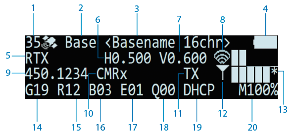
| Line 1: Mode, Base station name | |
| 1 Number of tracked satellites. | 3 Base station name and code. |
| 2 Operation mode (Base). | 4 Internal battery state. |
| Line 2: Position | |
| 5 Position solution. | 8 Wi-Fi signal strength (RSSI bars): * = Internet connection (Wi-Fi). A = Access Point mode enabled. |
| 6 Horizontal precision estimate. | |
| 7 Vertical precision estimate. | |
| Line 3: Correction output | |
| 9 UHF transmit frequency/channel. | 12 LTE signal strength (RSSI bars). |
| 10 Output correction type. | 13 * = Internet connection (LTE). |
| 11 TX flashes when corrections are transmitted. | |
| Line 4: Constellations, ethernet, logging | |
| 14 Number of tracked GPS satellites (G). | 18 Number of tracked QZSS satellites (Q). |
| 15 Number of tracked GLONASS satellites (R). | 19 Wired Ethernet connection mode. |
| 16 Number of tracked BeiDou satellites (B). | 20 Available internal memory (Logging). |
| 17 Number of tracked Galileo satellites (E). |
|
Radio mode
450 MHz repeater
This example shows a receiver in Radio mode with a 450 MHz repeater:
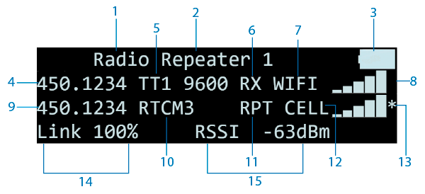
| Line 1: Mode | |
| 1 Operation mode (Radio). | 3 Internal battery state (flashes if charging.) |
| 2 Radio mode: (Repeater). The repeater number also shows. | |
| Line 2: Incoming correction source | |
| 4 Incoming UHF transmit frequency of the internal radio. | 7 Wi-Fi signal strength (RSSI bars). |
| 5 Radio protocol and baud rate. | 8 * shows if connected to the internet. |
| 6 Correction stream source. RX flashes when a correction is received. | |
| Line 3: Output, correction type | |
| 9 Output channel of internal UHF frequency. | 12 LTE signal strength (RSSI bars). |
| 10 Output correction type (if known). | 13 * shows if connected to the internet. |
| 11 RPT flashes when repeater is transmitting. | |
| Line 4: UHF quality | |
| 14 Link % quality of repeater transmission. | 15 Received Signal Strength (RSSI) for 450 MHz UHF reception. |
900 MHz Rebroadcaster
This example shows a field radio rebroadcasting from NTRIP Client 1 to NET13 900 MHz:
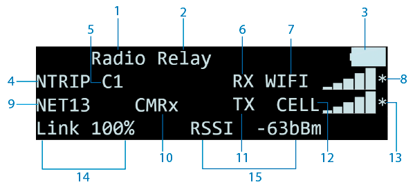
| Line 1: Mode | |
| 1 Operation mode (Radio). | 3 Internal battery state (flashes if charging). |
| 2 Radio mode: (Relay). | |
| Line 2: Incoming correction source | |
| 4 UHF transmit frequency/channel of the internal radio. | 7 Wi-Fi signal strength (RSSI bars). |
| 5 Radio protocol and baud rate. | 8 * shows if connected to the internet. |
| 6 Correction stream source. RX flashes when Relay is receiving. | |
| Line 3: Output, correction type | |
| 9 Internal UHF output channel. | 12 LTE signal strength (RSSI bars). |
| 10 Output correction type (if known). | 13 * shows if connected to the internet. |
| 11 TX flashes when Relay is transmitting. | |
| Line 4: UHF quality | |
| 14 Link % quality of relay transmission. | 15 Received Signal Strength (RSSI) for 900 MHz reception. |
