Lines
The lines you want to stake out must be part of a design map in the currently loaded design or measured lines present in the currently open work order. There are multiple ways to get these lines into a design, in addition to measured lines:
-
From a DXF, DWG, or VCL design map with lines containing lines, linestrings, or polylines.
-
By creating lines from points using the COGO functions.
To stake a line object:
-
From the Main map screen, tap the Home button and then tap Stake.
-
Select a line by tapping on a line in the Select Object screen, or by using the list icon
 on the top right of the screen and then select a line in the Lines tab. Alternatively, select the line directly from the main map screen (tap and hold and then select Stake Line from the pop-up menu). If there is more than one object available in this area, a list of different objects appears that you can select from.
 -
When using the Trimble Business Center software, names can be assigned to lines to improve the orientation.
You can also create a new line from points in your loaded design or work order by tapping the New line
 icon in the top right corner of the screen:
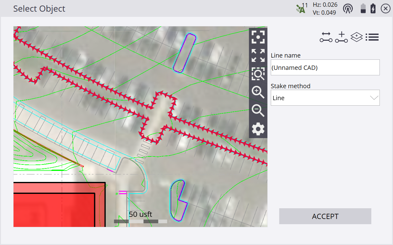
-
If necessary, before confirming the selection, change the line direction using the
 button on the top right of the screen. This function is not available for lines selected by tap and hold.
 -
Different stake methods (side slope and catch point) are available. See Slope staking.
-
When Fixed is the selected Station mode, enter the station to be staked out or tap on the line where you want to stake it and then tap ACCEPT. To change the settings related to the line staking, such as desired horizontal and vertical offsets, stakeout elevations, station advancement interval and if corner/tangent points should be created, tap
 . For Random mode, it is not necessary to select a station and offset.
 -
The map view then guides you to the point. To help you find the point, the guide arrow in the upper right side needs to point up the screen to show that you are traveling directly toward the point. You can turn the guide arrow off and on in the Design tab of the Map Options screen, accessed by tapping
 . The information bars at the top of the screen can be customized using the Info Bar/Panel option. The display shows the design elevation for the point, the amount of cut or fill required to get to that elevation, and how far and in what direction you need to travel to get to the point.
 -
The default map view has the direction north pointing up. You can change this so that the guide arrow is pointing in the direction you are walking by changing the map rotation in the Map Options screen. It is recommended to turn on the cut/fill lightbar in the top or bottom panel on the left to graphically show the cut and fill.
-
For Fixed mode, when you are close to the selected line point, the software switches into the Fine Stake mode. Additional guidance arrows appear on the top right corner of the main panel to indicate the remaining distance in each direction. The screen is oriented to the last moving direction before the Fine Stake mode was activated if map rotation in travel direction was selected.
-
When staking with a GNSS receiver, the fine navigation arrows will be displayed in a north "up" orientation, relative to the receiver's heading for a tilt-compensated receiver or in the direction of approach at the time the fine navigation arrows appear. Set this Stakeout guide option in the Design tab of the Map Options screen.
-
For staking performed with a total station, the fine navigation arrows will be oriented depending on the connection method to the total station. The direction of the fine stakeout guide will be in the direction of approach when the fine navigation arrows appear if Approach Orientation is selected. If North/Instrument Orientation is selected, the behavior will be as outlined below.
-
For Bluetooth and cable connections, the directions will be as if you were standing behind the total station looking towards the point or prism.
-
For radio connections, the directions will be as if you were standing at the prism pole looking towards the total station.
-
-
After tapping Measure, a stakeout report appears. The software creates a Stake Marker report. A graphical diagram shows how to put an elevation mark on the stake. The software does all the calculations for you. The way the software calculates the elevation mark and cut/fill depends on the stakeout settings in the Trimble icon menu. The software remembers which tab of the stakeout report was last viewed and opens the same tab after staking the next point.
-
Instead of staking a certain station it is also possible to stake a line at random stations using the buttons on the status bar on the right side of the main panel:
Tap...
to...

stake at fixed station intervals starting at a certain station.

stake at random and arbitrary station intervals anywhere along the line, based on your current station location perpendicular to the line.
The fine stakeout guide arrows will not appear when in random mode.
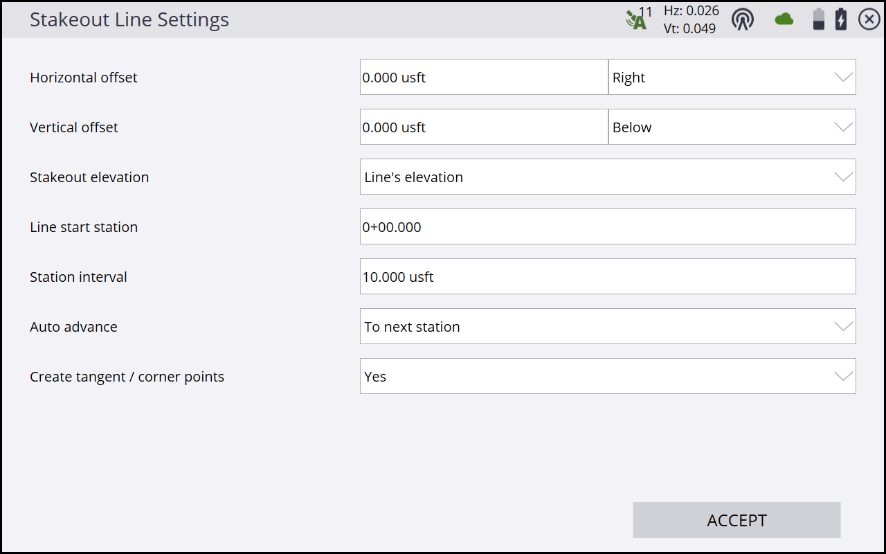
Settings available for staking lines include options to enter a horizontal and vertical offset for the stakeout line. The line elevation can be defined using different methods and the start station, station interval (increment distance), and whether or not to automatically advance to the next station can also be determined. If a horizontal offset is applied and yes is selected in the Create tangent/corner points selection menu, three stakeout points are created at each corner to help you stake out the lines. Access these settings from the Home menu under Stake / Line settings or by tapping the Line Settings button ![]() on the Select Line Station selection screen or in the top left of the main panel.
on the Select Line Station selection screen or in the top left of the main panel.