Drill Plan Settings
Use these options to:
- Set defaults that will be used when you create different types of drill plans for DPS900.
- Specify drill hole settings for a specific drill plan you are creating.
To access the settings:
- Do one of the following:
- When creating or editing a specific drill plan, click Edit Settings.
- To set defaults for future drill plans, select Project Settings. Then click Computations and then Drill Plan in the left pane.
|
Display Options |
|
|
Drill Holes |
|
| Blast hole color |
Select a color for the lines/cylinders indicating blast holes in graphic views. |
| Split hole color |
Select a color for the lines/cylinders indicating split holes. |
| Extra blast hole color |
Select a color for the lines/cylinders indicating the extra blast holes. |
|
As-Drilled Holes |
|
| As-drilled blast hole color |
Select a color for the lines/cylinders indicating imported as-drilled blast holes in graphic views. |
| As-drilled split hole color |
Select a color for the lines/cylinders indicating imported as-drilled split holes. |
|
Marking |
|
| Start point color |
Select a color for the markers (dots) indicating the points at which drill holes begin. |
| End point color |
Select a color for the markers (dots) indicating the points at which drill holes end. |
| Rock surface point color |
Select a color for the markers (diamonds) indicating where drill holes intersect a rock surface. |
|
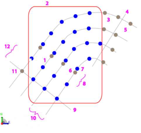
Boundary |
|
Note: This boundary drill plan is using a row-based (variable hole spacing) grid type. |
|
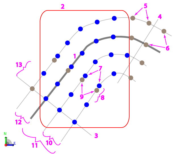
Corridor |
|
|
|
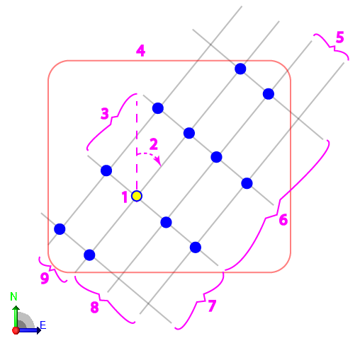
Grid |
|
|
|
Reference Line |
|
|
|
General |
|
|
Name |
Type a base name for new drill plans as you want them to appear in the Create Manual Drill Plan command, Project Explorer, and in DPS900. This name can be edited when you create Manual drill plans. |
|
Default layer for holes |
Specify the layer to use when adding drill holes to a drill plan. This layer can be edited when you create manual drill plans. |
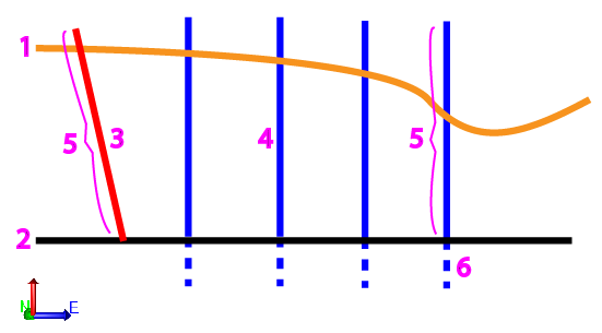
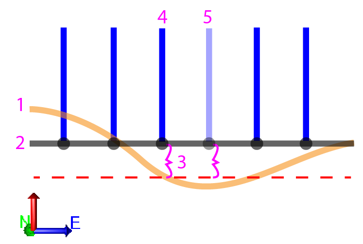
| Display length |
Specify the hole length (from start point to end point) to use when initially creating either blast or split drill holes for a Manual drill plan.
|
| Minimum hole length |
Specify the shortest total length (from rock point to subdrilling point) that all holes must be. |
| Maximum distance above rock |
Specify the maximum distance that a drill hole’s design point can be above the rock surface. Drill holes are not created where their design points would be farther above the rock surface than this tolerance.
Note: Because design points should not typically lie above a rock surface, these drill holes are only created to account to potential inaccuracies in the rock surface model; it is better to create a planned drill hole where it may not actually be needed than vice versa. |
| If no side slope instructions are present... |
(Corridor drill plan only) ...treat the outermost template instructions as ties - If none of the corridor instructions are a Side slope type, check this box to have them act as tie segments to the rock surface anyway. See Create a Corridor Drill Plan for details. |
|
Blast Holes |
|
| Build blast holes |
(Corridor drill plan only) Uncheck this box to prevent the creation of blast holes along with the split holes. |
| Hole diameter |
Specify the cylindrical diameter of drill holes (in inches or millimeters based on your project units). This diameter is shown in graphic views. |
| Hole direction |
(Corridor or Reference Line drill plan only)
|
| Hole orientation |
(Boundary, Grid, or Manual drill plan only) Specify the azimuth of drill holes (in the Plan View). The zero direction is north. Positive angles are measured clockwise from 0 to <360 degrees. |
| Hole inclination |
Specify the vertical angle of drill holes. The zero angle is straight down (nadir). Inclination should typically be between 0 and 45°. Note: In a Manual drill plan, you can vary the orientation and inclination for each drill hole you add, but any single drill hole cannot have more than one inclination (variable inclination). |
| Duplicate design point tolerance |
Specify a 3D distance within which duplicate hole design points will not be created; two blast hole or split hole design points cannot be this close to each other. |
| Spacing method |
(Corridor drill plan only) Select an option for spacing the blast holes:
|
| Staggered |
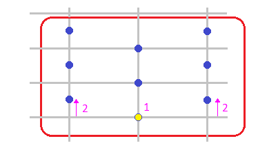
(Grid and boundary drill plan only) Click the Staggered box to offset every alternate blast hole along the row by 50% of the row spacing. The blast hole columns will follow the column spacing. Staggering begins forwards and backwards from the grid origin.
Note: This setting is not available when Drill Plan Type is set to Boundary and Grid type is set to Row-based (variable hole spacing). |
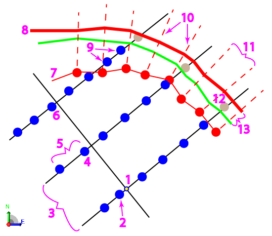
| Row/station spacing (burden) |
In the Method list, select how you want tospecify the distance along the alignment (station) between rows (cross-sections), from the start station to the end station.
Note: When the burden is defined by this factor, it is still compatible with the factor of burden subdrilling setting, and the alternative hole spacing method for corridors (max spacing along rows is determined by a factor of the burden).
|
|
Column/Maximum hole spacing |
(Boundary or Corridor drill plan only)
For a Corridor drill plan, specify the maximum distance between holes in a row. |
| Spacing factor |
Depending on which Spacing factor you selected above, specify a factor to apply to the row or station spacing of drill holes. |
| Extra hole edge tolerance |
(Boundary or Corridor drill plan only) For a Boundary drill plan, specify a planimetric distance from the boundary within which blast holes will not be created. For a Corridor drill plan, specify a distance from the rock surface’s intersection with the split hole line within which blast holes will not be created. |
| Row spacing (burden) |
(Boundary or Grid drill plan only) Specify the distance between each row and each column of drill holes in the drill plan's grid. |
| Hole spacing |
(Grid drill plan only) Specify the distance between holes within a row in the grid. |
| Rows ahead |
(Grid drill plan only) Enter the number of drill hole rows to create in the grid in front of the drill hole at the origin point. |
| Rows behind |
(Grid drill plan only) Enter the number of drill holes rows to create behind the drill hole at the origin point. |
| Holes to the left |
(Grid drill plan only) Enter the number of drill hole columns to create in the grid left of the drill hole at the origin point. |
| Holes to the right |
(Grid drill plan only) Enter the number of drill hole columns to create in the grid right of the drill hole at the origin point. |
| Spacing along lines |
(Reference line drill plan only) Specify the distance between blast holes along the reference line. |
| Offset lines to the left |
(Reference line drill plan only) Specify the number of offset lines of holes to the left of the reference line. This setting is disabled if Build split holes is set to Yes and Side is set to Right on the Split Hole tab. |
| Offset lines to the right |
(Reference line drill plan only) Specify the number of offset lines of holes to the right of the reference line. This setting is disabled if Build split holes is set to Yes and Side is set to Left on the Split Hole tab. |
| Segment end point tolerance |
(Reference line drill plan only) Specify a distance to a line segment’s end point within which a blast hole will be snapped to that end point’s location. |
|
Split Holes (none for Grid drill plan) |
|
| Build blast holes |
(Corridor drill plan only) Uncheck this box to prevent the creation of blast holes along with the split holes. |
| Build split holes |
(Reference Line drill plan only) Check this box to build split holes. |
| Build blast holes on reference line |
(Reference Line drill plan only) Check this box to build blast holes along the reference line. |
| Hole diameter |
Specify the cylindrical diameter of drill holes (in inches or centimeters based on your project units). This diameter is shown in graphic views. |
| Hole direction |
(Reference Line drill plan only)
|
| Hole orientation |
(Manual drill plan only) Specify the azimuth of drill holes (in the Plan View). The zero direction is north. Positive angles are measured clockwise from 0 to <360 degrees. |
| Use blast hole setting |
(Reference Line drill plan only) If Build split holes is checked above, keep this box checked to use the same inclination as the blast holes. Otherwise, uncheck this box and specify a vertical angle for the split hole inclination. |
| Hole inclination |
Specify the vertical angle of drill holes. The zero angle is straight down (nadir). Inclination should typically be between 0 and 45°. Note: In a Manual drill plan, you can vary the orientation and inclination for each drill hole you add, but any single drill hole cannot have more than one inclination (variable inclination). |
| Duplicate design point tolerance |
Specify a 3D distance within which duplicate hole design points will not be created; two blast hole or split hole design points cannot be this close to each other. |
| Maximum hole spacing |
(Boundary drill plan only) Specify the maximum distance between split holes along the boundary line. |
| Station spacing |
(Corridor drill plan only) Specify a distance between split hole rows (cross-sections) along the alignment (station), from the start station to the end station. |
| Spacing along lines |
(Reference Line drill plan only) Specify a distance between split holes along the reference line, from the start station to the end station. |
| Segment end point tolerance |
(Reference Line drill plan only) Specify a distance to a line segment’s end point within which a split hole will be snapped to that end point’s location. |
|
Subdrilling |
|
| Include depth percentage Depth percentage |
Check the box to extend drill hole lengths by a percentage of the hole length (to achieve a subdrilling depth, usually beyond the design surface). This is only applied if a rock surface is specified for the drill plan. |
| Include factor of row/station/offset spacing (burden) |
(not in Manual drill plans) Check the box to extend drill hole lengths by a percentage of the hole length (to achieve a subdrilling depth, usually beyond the design surface). This is only applied if a rock surface is specified for the drill plan. Then specify the factor of the hole length to add. |
| Include blast hole constant Blast hole constant |
Check the box to add a constant depth to the subdrilling depth of blast holes. Then specify the depth to add. |
| Include split hole constant Split hole constant |
Check the box to add a constant depth to the subdrilling depth of split holes. Then specify the depth to add. |
|
Quality |
|
| Diameter tolerance |
Specify the maximum diameter difference between a planned hole's diameter and its associated as-drilled hole's diameter that is allowed for the as-drilled hole to be considered passable in the Drill Hole Quality Report. |
| Blast hole design point tolerance Method Factor of burden |
(Method is not in Manual drill plans) In the Method list, select how you want tospecify the maximum distance between a planned blast hole's design point (coordinate) and its associated as-drilled blast hole's design point (coordinate). This affects whether an as-drilled hole is considered passable in the Drill Hole Quality Report.
|
| Split hole design point tolerance |
(not in Grid drill plans) Specify the maximum 3D distance between a planned split hole's design point coordinate and its associated as-drilled split hole's design point coordinate that is allowed for the as-drilled hole to be considered passable in the Drill Hole Quality Report. |
|
Estimation |
|
| Average penetration rate |
Estimate the average rate at which split holes and blast holes can be drilled in your project's distance units per hour. |
| Cost per hour |
Estimate the cost to your company to drill either split or blast holes for an hour. Note: For drill planning cost estimates, this program displays the currency symbol and format that you have set in Microsoft Windows® Regional and Language Options. The units and calculations, however, are not associated with a specific currency, so if a project is opened on a computer with different regional settings, those currency symbol and formats are used, but no conversion between currencies has been made. |
| Cost factor |
Apply a positive factor to the drilling cost per hour to account for any real-world variables that might negatively affect the drilling cost per hour. |