Create a Drill Plan Based on a Corridor
Use the Create Drill Plan command to create a gridded drill plan of blast holes along a corridor design. This type of drill plan can be constrained between a start and end station and by a boundary. Corridor drill plans also support benching, which allows you to create successive ledges by drilling split holes one vertical level at a time; one set of drill holes is created for each bench.
Benching:
Benching allows you to drill split holes in successive vertical levels to create ledges around the edge of the drilling area (once it is blasted and excavated); this enables you to blast holes in tiers of shorter depths.
|
|
|
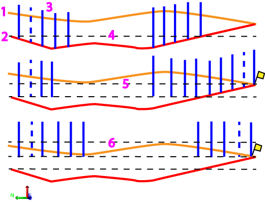
Figure: Benching levels
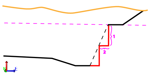
You can specify a Maximum last bench height, which allows the last bench (closest to the rock surface to exceed the Bench Height to avoid creating benches with short heights). For example, when excavating to a depth of 22 m using a bench height of 10 m and a maximum last bench height of 15 m, the first bench is created with a height of 10 m from the design surface, and the second bench with a height of 12 m. If, however, the excavation depth is 27 m, two benches of 10 m and one of 7 m are created, since 17 m would exceed the 15 m last bench height limitation.
Note: When creating benches, the first bench is the lowest one, nearest to the corridor/design surface. When blasting and excavating benches, the first bench is the top one, nearest to the existing ground or rock surface.
|
Figure: Benching height and width |
|
Prerequisites:
- Licensed module; See the Subscription Plans page. For a license matrix by command, see the License page in the TBC Community. Also see View and manage licensed features.
- Corridor
To access the command:
- Select Create Drill Plan in Drill Pile Compact > Drilling.
- Right-click Drill Plans in the Project Explorer and select Drill Plan.
To create a surface by reference line drill plan:
- Select Corridor in the Drill Plan Type list.
- In the Name box, type an identifier for the drill plan as you want it to appear in the Project Explorer and to the DPS900 operator.No other drill plan can use the same name.
- Select the layer on which you want the drill holes to reside.
- In the Corridor list, select the corridor design surface on which to base the drill plan.
- If applicable, select the surface (or strata) that represents the top of a rock strata that the drill holes will penetrate in the Rock surface list.
- To limit the plan to a specific area, click in the Boundary box and pick the line that you want to use as the image boundary in the Plan View. Linestrings, polylines, alignments, and boundaries can be used as the clipping boundaries.
- To constrain the drilling to a certain station range, specify the range in the Begin station and End station boxes.
- To use benching in the drill plan, check the Build benches box. Otherwise, skip to step 11.
- In the Bench height box, specify the height of benches to be created. Benches are measured upwards from the design surface.
- To allow the last/top bench to be higher that the standard bench height so you do not get a short final bench, specify a Maximum bench height (factor). This setting (which accepts values between 1 and 2) merges the top two benches of a corridor drill plan into one bench if the height of the top bench is lower than the combined height of the top two benches multiplied by the factor.
- To prevent short holes from being created by extending holes in a lower bench to cover the rock, specify a Maximum hole extension.
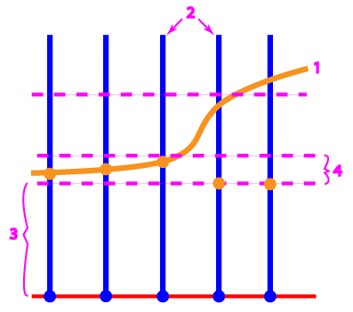
- rock surface
- drill holes
- bench height
- maximum hole extension
Note: This value cannot be greater than 50% of the benching height.
Click the Edit Settings button and specify settings for a basic drill plan (see Drill Plan Settings for descriptions of the options).
- Once you are done specifying settings, click OK. The drill plan appears under Drill Plans in the Project Explorer and the grid of drill holes appears in graphic views.
How tie segments and the placement of split, blast, and extra holes are determined:
In no benching has been defined, this is the general method used for determining how the drill plan is configured at each station along the corridor.
- The nearest downstation corridor template is inspected.
- The outermost (left and right) template instructions are identified.
- If typed as Side slope instructions, in cut, intersecting with a rock surface, the outermost segments are identified as tie segments. A tie segment is the portion (between nodes) of a corridor cross-section that corresponds to an outer-most side slope template instruction that intersects in cut with a rock surface.
Note: Tie segments in the middle of a corridor template (not the left-most or right-most) are ignored.
- The points at which the tie segments connect to the bottom of the corridor template are identified as ditch points.
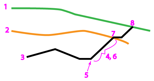
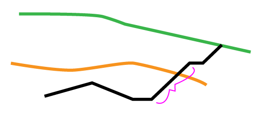
- existing ground surface
- rock surface
- corridor template
- right-most template Side slope instruction
- ditch point
- tie segment
- tie to rock surface
- tie to existing ground surface
Note: The same logic applies when searching for the left-most tie segment.
- Cross-sections where drill holes will be created are ‘sliced’ along the corridor from the Start station to the End station based on the Row/station spacing settings for the drill plan (from Edit Settings).
- At each station where a row of drill holes will be created, the cross-section segments that correspond to the tie slope segments of the template are identified as cross-section tie segments. Corresponding ditch points are identified on the cross-sections as well.
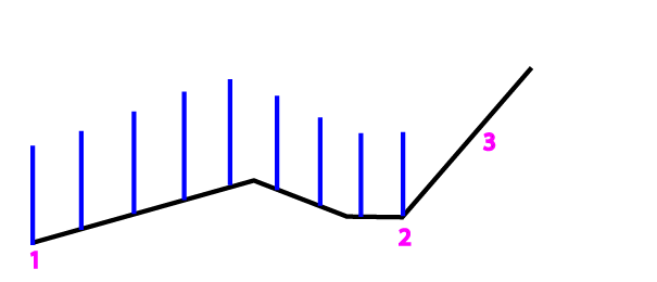
- Split holes are created coincident with the tie segments at each cross-section if the tie segment/slope is steeper than 45 degrees.
- Blast holes are created along the bottom of each cross-section between the tie segments/ditch points.
- Extra blast holes are created up the tie segments at each cross-section. If the tie segment's slope is steeper than 45 degrees, extra blast hole design points lie along the tie slope. If the tie segment's slope is shallower/flatter than 45 degrees, normal blast holes are added instead. A normal blast hole is added at each intersection of the rock with the tie slope. This hole is immune from the "extra hole edge tolerance".
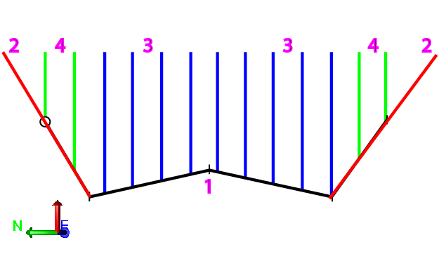
- corridor template/cross-section derived from the template
- split holes (red)
- blast holes (blue)
- extra blast holes (green)
If no template instruction is a side slope type:
- If no template instruction is a Side slope type, you can allow the outermost instruction (if in cut and intersecting with the rock surface) to be considered a side slope by checking the If no side slope instructions are present, treat the outermost template instructions as ties box. If you do this, tie segments and the placement of split, blast, and extra drill holes are determined as described above.

None of these segments are side slope instructions.
- If no template instruction is a side slope type, and you do not check the box described above, the outermost template instructions are extended up as the split hole inclinations. Blast holes are created across the width of the entire corridor template, and extra blast holes are created up from the split hole inclinations.
-
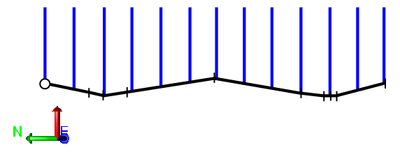
Notes on blast holes:
- No blast holes are created outside a boundary.
- Blast holes are only created if their design points are planimetrically coincident with the rock surface (the rock surface is directly above/below their design point), or if their vectors intersect the rock surface.
- At each cross-section, blast holes are created along the bottom-most instructions of the corridor between the ditch points.
- left-most point (or tie ditch point) to
- right-most point (or tie ditch point)
- tie slope
Scenarios:
- If the distance from B to C is less than the Maximum hole spacing, a blast hole is created halfway from B to C.
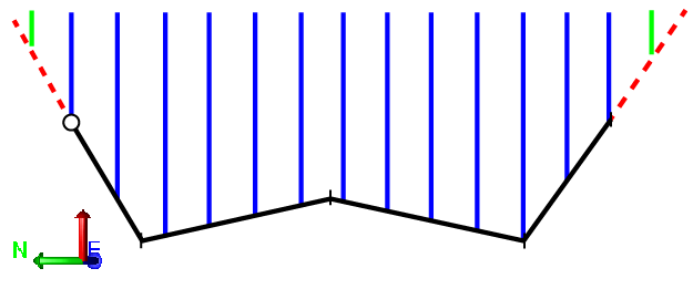
Notes on Extra blast holes
- At each cross-section, extra blast holes are created along the split line or split line inclinations.
- Extra blast holes are only created if their design points are planimetrically coincident with the rock surface (the rock surface is directly above/below their design point), or if their vectors intersect the rock surface.
Scenarios:
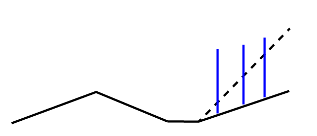
- If you select a rock surface that extends beyond the outer-most (left or right) segments (or tie ditch points), extra blast holes are created beyond the tie point. These extra blast holes use split hole subdrilling values.
- If the outer-most point is not a ditch point, the extra blast hole’s design points are placed along the split hole’s inclination.
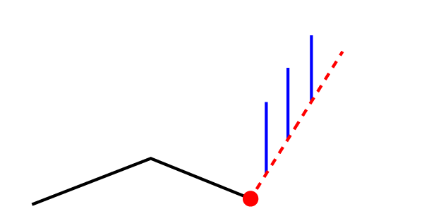
- split line inclination
- extra blast holes
- If the outer-most point is a ditch point, and the tie slope is steeper than 45 degrees, the extra blast hole’s design points are placed along the tie slope.
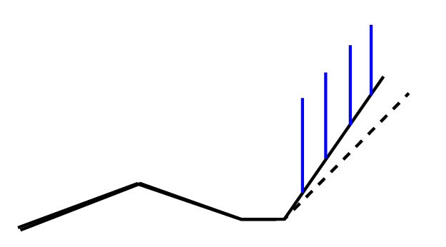
- If the tie slope is shallower/flatter than 45 degrees, standard blast holes are created instead.
Notes on split holes:
- At each cross-section, split holes are created coincident with or projected from the outermost template's sidelsope segment.
- Split holes are oriented towards the corridor’s alignment/centerline.
- Split holes are not created if their design point is not below the rock surface (rock surface is not present directly above/below design point) and their vector does not intersect the rock surface.
Scenarios:
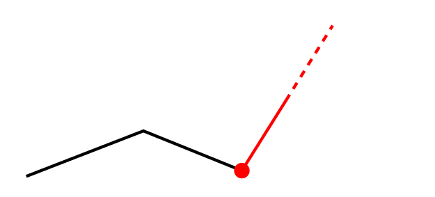
- If the outer-most point is not a tie ditch point, the drill plan setting for split hole inclination is used.
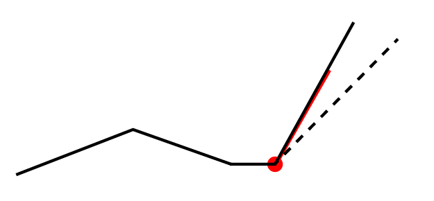
- If the point is a tie ditch point, and the tie slope is steeper than 45 degrees, the slope of the tie is used for the split hole inclination.
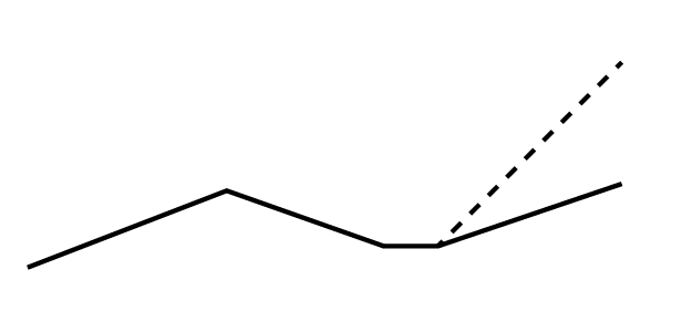
- If the tie slope is shallower/flatter than 45 degrees, then a split hole is not created.
Dependencies:
- Drill hole start, design, and rock intersection points are dependent on the original ground, rock, and finished design surfaces. If these surfaces change, the coordinates of drill holes points will update to reflect the change.
