Create a Drill Plan Based on a Grid
Use the Create Drill Plan command to create a drill plan based on an origin, design surface, rock surface, and a uniform or staggered spacing (rows and columns) of blast holes. This type of drill plan can be constrained by a boundary.
|
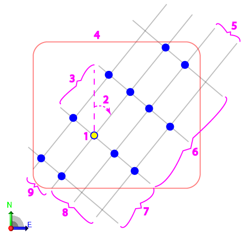
Figure: Parts of a grid drill plan |
|
Prerequisites:
- Licensed module; See the Subscription Plans page. For a license matrix by command, see the License page in the TBC Community. Also see View and manage licensed features.
- Finished design surface
To access the command:
- Select Create Drill Plan in Drill Pile Compact > Drilling.
- Right-click Drill Plans in the Project Explorer and select Create Drill Plan.
To create a grid-based drill plan:
- Select Grid in the Drill Plan Type list.
- In the Name box, type an identifier for the drill plan as you want it to appear in the Project Explorer and to the DPS900 operator.No other drill plan can use the same name.
- Select the layer on which you want the drill holes to reside.
- Select the surface representing the finished design surface that the drill holes will form in the Design surface list.
- If applicable, select the surface (or strata) that represents the top of a rock strata that the drill holes will penetrate in the Rock surface list.
- To limit the drill plan to a specific area, click in the Boundary box and pick the line that you want to use as the boundary in the Plan View. Linestrings, polylines, and boundaries can be used for clipping. No blast holes are created outside the boundary.
- In the Plan View, pick an origin point or type a coordinate in the Origin point box to specify the location/drill hole from which the grid will emanate based on the settings specified in step 8.
Depending on how many rows ahead and behind, and holes to the left and right, the origin may be in the center of the grid, on one side, or on a corner.
- In the Orientation box, specify the angle of the grid. Zero is north and positive rotation angles are clockwise.
- Click the Edit Settings button and specify settings for the drill plan (see Drill Plan Settings for descriptions of the options).
- Once you are done specifying settings, click OK. The drill plan appears under Drill Plans in the Project Explorer and the grid of drill holes appears in graphic views.
Dependencies:
- Drill hole start, design, and rock intersection points are dependent on the original ground, rock, and finished design surfaces. If these surfaces change, the coordinates of drill holes points will update to reflect the change.
