Create a Drill Plan Based on a Reference Line
Use the Create Drill Plan command to create a gridded drill plan of blast holes (and optionally split holes) along and offset from a reference line. This type of drill plan can be constrained between a start and end station and by a boundary.
|
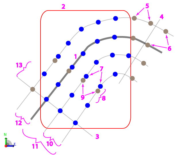
Figure: Parts of a line-based drill plan |
|
Prerequisites:
- Licensed module; See the Subscription Plans page. For a license matrix by command, see the License page in the TBC Community. Also see View and manage licensed features.
- Finished design surface
- 3D reference line (linestring, polyline, breakline, circle, or boundary)
To access the command:
- Select Create Drill Plan in Drill Pile Compact > Drilling.
- Right-click Drill Plans in the Project Explorer and select Create Drill Plan.
To create a surface by reference line drill plan:
- Select Reference Line in the Drill Plan Type list.
- In the Name box, type an identifier for the drill plan as you want it to appear in the Project Explorer and to the DPS900 operator.No other drill plan can use the same name.
- Select the surface representing the finished design surface that the drill holes will form in the Design surface list.
- If applicable, select the surface (or strata) that represents the top of a rock strata that the drill holes will penetrate in the Rock surface list.
- In the Reference line box, pick a 3D line on which the drill plan will be based (as the plan's centerline).
- To limit the plan to a specific area, click in the Boundary box and pick the polyline that you want to use as the boundary in the Plan View. Linestrings, polylines, and boundaries can be used for clipping. No blast holes are created outside the boundary.
- In th Begin station box, specify the station along the reference line that the starting hole position should be extended from.
- In the End station box, specify the station along the reference line that the last hole position should be extended to.
- Click the Edit Settings button and specify settings for the drill plan (see Drill Plan Settings for descriptions of the options).
- Once you are done specifying settings, click OK. The drill plan appears under Drill Plans in the Project Explorer and the grid of drill holes appears in graphic views.
Dependencies:
- Drill hole start, design, and rock intersection points are dependent on the original ground, rock, and finished design surfaces. If these surfaces change, the coordinates of drill holes points will update to reflect the change.
