Create a Drill Plan Based on a Boundary
Use the Create Drill Plan command to create a gridded drill plan (drill hole pattern) within a boundary. Split holes are created (facing perpendicularly inward) along the boundary line and blast holes are created within the bounded area. The grid's columns are fixed, but the row spacing can use fixed or dynamic spacing (which adjusts to the width between holes to avoid adding extra holes near or outside of the boundary). This drill plan type allows you to drill blast holes to a design surface or to a single benching elevation.
|
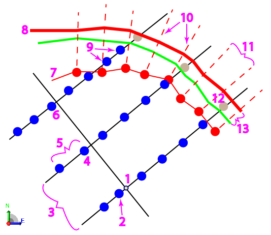
Figure: Parts of a boundary drill plan |
|
Benching:
Benching allows you to drill split holes in successive vertical levels whereby ledges are created around the area's edge (once the area is blasted and excavated). This drill plan type allows you to drill blast holes to a design surface or to a single bench elevation so you can drill, blast, and remove material to a specific level (bench) before drilling to the final design surface level.
|
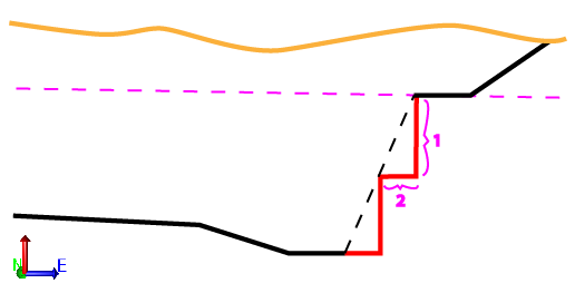
Figure: Benching height and width |
|
Prerequisites:
- Licensed module; See the Subscription Plans page. For a license matrix by command, see the License page in the TBC Community. Also see View and manage licensed features.
- Finished design surface
- Boundary line
To access the command:
- Select Create Drill Plan in Drill Pile Compact > Drilling.
- Right-click Drill Plans in the Project Explorer and select Create Drill Plan.
To create a surface by boundary drill plan:
- Select Boundary in the Drill Plan Type list.
- In the Name box, type an identifier for the drill plan as you want it to appear in the Project Explorer and to the DPS900 operator.No other drill plan can use the same name.
- Select the layer on which you want the drill holes to reside.
- Select the surface representing the finished design surface that the drill holes will form in the Design surface list.
- If applicable, select the surface (or strata) that represents the top of a rock strata that the drill holes will penetrate in the Rock surface list.
- Click in the Boundary box and pick the polyline that you want to use as the boundary in the Plan View. A linestring, polyline, alignment, or boundary can be used as the bounding line. No blast holes are created outside the boundary.
- In the Bench elevation box, specify the elevation of a single bench to be created between the rock surface and the design surface.
Note: If you specify both a benching elevation and a design surface, each drill hole's design point will be placed at the higher (in elevation) of the two.
- Select how you want the grid of drill holes to be formed:
- Grid (fixed hole spacing) - Select this to create a uniform grid of rows and columns of drill holes. This will not adjust hole locations in relation to the boundary at the edge of the drilling area. You can choose to stagger the blast holes, by alternating the initial row position while maintaining row and column spacing, see Drill plan settings.
- Row-based (variable hole spacing) - Select this to maintain rows of drill holes, but vary the (formerly column) spacing based on the outside hole's distance to the boundary.
- Based on the selected grid type, choose a bearing for either the grid's columns or rows:
- Orientation (column) - Zero creates north/south columns, and positive rotation angles are clockwise.
- Orientation (row) - Zero creates north/south rows, and positive rotation angles are clockwise.
- In the Plan View, pick an origin point or type a coordinate in the Origin point box to specify the location from which the grid will emanate based on the settings specified in step 9. The grid of drill holes will extend in each direction from the origin to the boundary.
- Click the Edit Settings button and specify settings for a basic drill plan (see Drill Plan Settings for descriptions of the options).
- Once you are done specifying settings, click OK. The drill plan appears under Drill Plans in the Project Explorer and the grid of drill holes appears in graphic views.
Scenarios:
- If the Grid type is Grid, holes are spaced at the Hole spacing setting along the row, with the 0 hole lining up with the origin point. Any holes outside the split hole boundary (but inside the outer boundary) are created as blast holes.
Dependencies:
- Drill hole start, design, and rock intersection points are dependent on the original ground, rock, and finished design surfaces. If these surfaces change, the coordinates of drill holes points will update to reflect the change.
