Run a Drill Hole Quality Report
Use the Drill Hole Quality Report command to see a summary and details on pairs of drill holes; the holes in a drill plan (planned holes) as compared to their corresponding as-drilled holes. Each as-drilled hole that is reported on is qualified as passing, failing, or requiring action (based on the tolerances in Project Settings). The Drill Hole Quality Report is generated as a Microsoft® Excel spreadsheet.
Prerequisites:
- License; See the Subscription Plans page. For a license matrix by command, see the License page in the TBC Community. Also see View and manage licensed features.
- As-drilled holes that include quality comparisons with planned drill holes. You can bring these holes into your project by:
- Importing an IREDES file of as-drilled holes into a project that already includes a drill plan of the same name with related planned holes
or
- Importing two IREDES files with drill plans of the same name: one with planned drill holes and one with related as-drilled holes
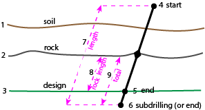
- Soil surface
- Rock surface
- Design surface
- Start point
- End point
- Subdrilling end point
- Length
- Rock length
- Total length
To access the command:
- Select Drill Hole Quality Report in Drill Pile Compact > Drilling.
To run a Drill Hole Quality Report:
- Select a drill plan that has an associated plan with as-drilled hole data in the Drill plan list. Corridor drill plans are listed per individual bench.
- Select an option in the As-drilled holes to include list:
- All holes - Select this to report on every pair of planned and as-drilled holes in the selected drill plan.
- Selected holes - Select this to report on a subset of the paired holes in the drill plan.
- Limit by station - Select this to report on pairs of drill holes between specific stations along an alignment in a Corridor drill plan or between specific distances along a line in a Reference Line drill plan. (This option only appears if you have a drill plan based on a corridor or reference line.)
- If you chose Selected drill holes, pick drill holes in a graphic view or click Options for additional selection methods.
- If you chose Limit by station, specify the Begin and End stations to report between.
- Click Apply if you want to run the report more than once, or click OK. The Drill Hole Quality Report opens in Excel.
Note: If you receive a message that there is no data to report, none of the selected holes in a drill plan have associated as-drilled hole data.
To modify the report:
- Do one of the following:
- Select (if on the main menu).
- Click the Report Options icon (if on a toolbar).
- Select Drill Hole Quality Report in the Reports list.
- In the Settings group, specify report options.
- Click Apply and then the icon on the pane's toolbar to run the report, or click OK to close the command.
|
Selected Report Components (Summary tab) |
|
|
Summary |
|
| Blast end-point tolerance |
For blast holes, this shows the maximum allowable distance between the planned hole's design point and the as-drilled hole (or the factor of burden multiplied by the burden) for the as-drilled hole to be considered passable quality. |
| Split end-point tolerance |
For split holes, this shows the maximum allowable distance between the planned hole's design point and the as-drilled hole (or the factor of burden multiplied by the burden)for the as-drilled hole to be considered passable quality. |
| Minimum hole length |
This shows the minimum allowable length for each as-drilled hole to be considered passable quality. |
| Diameter tolerance (mm/inches) |
This shows the maximum allowable difference in diameter between planned holes and as-drilled holes for the as-drilled hole to be considered passable quality. |
| Estimated average penetration rates |
For all as-drilled holes, this shows the average of their lengths divided by drill times (ft/m per second). Note: This estimate can help you determine how long to schedule work for drilling machines. |
|
Totals |
|
| Total drilling length |
This shows the cumulative length of all drill holes listed in the report. |
| Average length of as-drilled |
This shows the total length of all as-drilled holes divided by the number of the as-drilled holes. |
| Average penetration rate |
This shows (separately for blast, split, and unknown holes) the cumulative drill hole length divided by the cumulative drilling time in ft/m per second. |
| Total drilling time |
This shows (separately for blast, split, and unknown holes) the cumulative, elapsed drilling time for all of the reported holes. |
|
Selected Report Components (Hole Data tab) |
|
|
Results are sorted in this order:
ID
Quality Test cells are also color-coded:
|
|
| Hole ID |
This shows the row:hole/column number (if column is applicable) |
| Hole type |
|
| Note |
If notes have been entered in the field they are shown at the end of the row for the appropriate drill hole. |
|
Planned hole |
|
| Length |
This shows the distance (from start point to end point) for each planned drill hole. |
| Start point |
This shows the coordinate on the rock surface where the start of drilling was planned for the hole (in northing, easting, elevation format). Note: If this value is blank, there was no intersection point on the rock surface. |
| End point |
This shows the coordinate on the finished design surface where the end of drilling was planned for the hole (in northing, easting, elevation format). |
| Station Offset |
If the selected drill plan is based on a reference line or a corridor, this shows the station (or distance along for a reference line) and offset of the planned hole. |
|
As-drilled hole |
|
| Start point |
This shows the coordinate on the rock surface where the drilling started (in northing, easting, elevation format). |
| End point |
This shows the coordinate on the finished design surface where the drilling finished (in northing, easting, elevation format). |
| Station Offset |
If the selected drill plan is based on a reference line or a corridor, this shows the station (or distance along for a reference line) and offset of the as-drilled hole. |
| Start time End time |
For all as-drilled holes, this shows their earliest start and latest end times (date/hh:mm:ss). Note: This is in local time |
| Drilling time |
This shows the difference between the as-drilled hole's, start time and the end time, in decimal hours. |
| Penetration rate |
This shows the distance units drilled (m or ft) per hour for each hole. |
|
Delta |
|
| Start point easting, northing, and elevation or Station |
These show the differences in northing, easting, and elevation between the planned and as-drilled hole start points. If the selected drill plan is based on a reference line or a corridor, this shows the differences in station (or distance along for a reference line) between the planned and as-drilled hole start points. |
| End point easting, northing, and elevation or Station |
These show the differences in northing, easting, and elevation between the planned and as-drilled hole design points. If the selected drill plan is based on a reference line or a corridor, this shows the differences in station (or distance along for a reference line) between the planned and as-drilled hole design points. |
| Orientation |
This shows the difference in azimuth (degrees) between the planned hole and the as-drilled hole. Positive rotation angles are clockwise. |
| Inclination |
This shows the differences in inclination (degrees) between the planned and as-drilled holes. Positive angles are measured counter-clockwise (when facing north). |
|
Error Vector |
|
| 3D Length |
This shows the length of the vector between the planned and as-drilled holes' start points. |
| Azimuth |
This shows the direction of the vector between the planned and as-drilled holes' start points. Zero is north and positive rotation angles are clockwise. |
|
Quality tests |
|
| Design Points |
This indicates whether the as-drilled hole's end point is within passable tolerance:
|
| Minimum length |
This indicates whether the as-drilled hole's length is of passable length. |
| Hole types |
This indicates whether the as-drilled hole's type is as planned. |
| Diameter tolerance |
This indicates whether the as-drilled hole's diameter is within passable tolerance. |
