Understanding Pile Planning for DPS900
Pile planning in Trimble Business Center enables you to:
- Create, edit, and delete various types of piles which can then be applied to specific piles when you create pile plans.
- Create a pile plan to send to DPS900, a Trimble drilling and piling system for road construction and pit mining; the pile plan helps the DPS900 machine operator navigate to pile locations (nearest, previous, next, or selected), and then guides him in hammering the piles at the planned orientation, inclination, and controlling embedment length.
- Create individual piles for a pile plan, specifying each pile's type, location, orientation, and inclination.
- Export pile plans to DPS900 as Project Link files (.vcl).
- Re-import files that contain the results of piling (as-built pile data) based on a specific pile plan.
- Report on the number of hammer blows (blow count) that were required to embed each as-built pile (in a pile plan) to its required resistance as compared to its planned resistance (blows/distance).
- Visualize both planned and as-built piles in the Plan View and 3D View.
- Import files that contain pile plans created in the field.
- Modify imported pile plans by adding, removing, and changing piles or pile types.
Prerequisites
- One or more licenses; See the Subscription Plans page. For a license matrix by command, see the License page in the TBC Community. Also see View and manage licensed features.
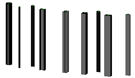
Pile Types
The types of piles you can create are based on parameters for these cross-sectional shapes:
- Cylinder, by specifying length, diameter, and wall thickness
- Sheet, by specifying length, width, and wall thickness
- H, by specifying length, width, and height
- I, by specifying length, width, and height
- Square, by specifying length, and width
- Rectangle, by specifying length, width, and height
- Custom (solid), by specifying length, and picking a custom, closed cross-sectional shape
- Custom (hollow/open), by specifying length, and picking a custom, open cross-sectional shape
All pile types are represented by 3D objects in graphic views.
Pile Plans
Pile plans are pile layouts that you can create manually or based on an imported points file. Pile plans appear in the Project Explorer. The attributes of a pile plan can be viewed and edited in the Properties pane, after which the plan can be rebuilt to account for the changes.
Piles
Each pile plan is composed of individual piles arranged in a pattern. Pile properties are dependent on parameters specified in the pile type. When the settings change after the plan is created, the piles update in graphic views to reflect the changes.
|
Figure: Parts of piling |
|
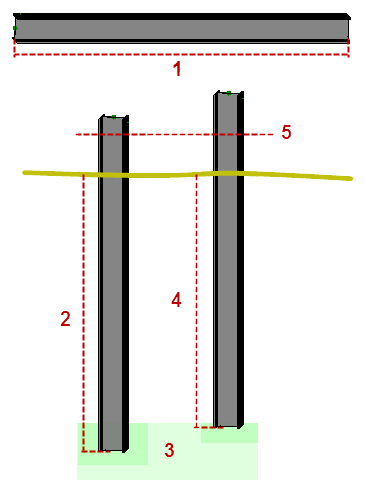
All piles have these properties:
- Pile ID - This identifier (name) is unique to each pile, and typically follows a specific naming pattern.
- Manufacturing ID - This is a manufacturer's own ID (not the pile plan name).
- Pile type - This categorizes a class of piles with a common cross-sectional shape, length, and other dimensions.
- Pile location - This is a coordinate defined at the pile's cut-off elevation.
- Pile cut-off elevation - This defines the elevation at the top of the pile after it has been embedded and then cut off to a standard height.
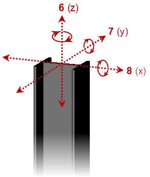
- Pile orientation - A pile is typically oriented with the structure it will support. In some cases, there may be two orientations: one aligned with each axis of a rectangular structure (i.e., parallel with the walls of the structure). Piles may also all have a unique orientation which is perpendicular to or tangential to a curvilinear reference line, e.g., for cofferdams or curved fascia, buildings, etc.
- Pile rotation - this defines the angle to which the pile should be turned on its vertical axis.
- Pile inclination angle - Vertical piles are designed to stop a structure from sinking. Inclined piles are designed to stop a structure from moving. A mix of inclined and vertical piles on a structure, such as a bridge, is common.
- Pile comments - These are used to define the structure that the pile is associated with, but can also be used for any additional information that is required.
- Expected embedment length - This defines the distance that the pile is intended to be driven into the ground.
- Minimum embedment length - This defines the minimum acceptable distance that the pile must be driven.
Pile Pre-boring
In order to embed a pile in a high-density soil, a 'pilot' hole may need to be drilled first. This is referred to as pre-boring, i.e., the creation of a hole that can be used to guide and assist in the placement of piles. These parameters can be specified for pre-bored holes:
- The diameter of the hole, expressed as a percentage of the pile's diameter. Typically, this is for cylindrical piles.
- The depth of pre-boring allowed, e.g., 16.5 m for a 20 m pile with an expected embedment of 18 m (to within 1.5 m of design pile embedment depth).
Importing and Exporting Pile Plans and Piling Results
Trimble Business Center enables you to export pile plans out as Project Link (.vcl) files, and then re-import a quality pile plan (As-built) file (.xml) once piling has been completed in the field (the as-built pile file name must match the exported pile plan's file name). You can also import files created by piling machines running DPS900 (if you build a simple pile plan in the field).
DPS900 supports importing .xml pile planning and as-built result files (both with just pile names and coordinates). DPS900 can also create a pile points file (.csv) with just pile name and coordinates.
