Smart Text Codes
Smart text is made up of abbreviated codes that, combined, specify what text values are displayed in a text label or annotation. These values typically, but not always, represent dynamic measurement values for selected objects. You can enter smart text codes with the assistance of the Insert Smart Text dialog or by typing them into the Text Editor.
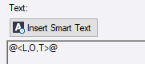
Each smart text code string must start by specifying a property type (see table below) followed by two or more "argument" codes that provide additional instructions specific to the selected property type. In the following simple example, the smart text specifies that the length (L for Length property) of a selected object (O for Object) is displayed along with a units suffix (T for true/yes, display a unit suffix):
@<L,O,T>@
Note: All smart text arguments strings must start with @< and end with >@.
Tip: When using smart text, you can include a "digit grouping symbol" to format (for example) "1000.00" as "1,000.00" by adding a minus sign before the smart text code for decimal precision formatting: change @<ELS,LD,T,1>@ to @<ELS,LD,T,-1>@ for example. This does not affect the decimal precision. Also see the To override the decimal precision section below.
|
Smart Text Fields/Arguments (7 possible codes between the 6 commas) All smart text codes must start with @< and end with >@ (ampersands and angle brackets). Within the angle brackets, each smart text code must start by specifying a property type followed by two or more "arguments" that provide additional instructions specific to the selected property type. A total of seven arguments separated by commas are possible; the default/minimum is three arguments, e.g., @<SS,T,F>@. An empty argument field is the same as "F" for false. When numeric, the extracted property value is shown in decimal units (unless overridden in field 7). |
|
| Three default fields/arguments shown in the Smart Text dialog | |
| 1 |
Specifies the property type value to display. E.g., northing, elevation, length, area, etc. |
| 2 |
Specifies the object or location (point in 2D space) to extract the property type value from. E.g., point, line, surface, leader, or text insertion point |
| 3 |
Specifies whether to display the units suffix. T = true/yes, F = false/no, P = base this argument on the project setting. (Quick Access toolbar > Project Settings > Units > Suffix) Exception: When using the surface slope code (SS) in the first field, this third field controls how the slope is computed/shown. If the 3rd value is "T" (e.g., "@<SS,T,T>@"), then the true triangle slope is displayed in the smart text. As you drag (move the rotation grip), the slope value does not change. If the 3rd value is "F", then the slope is computed in the direction of the text. As you drag, both slope values will change as the text is moved across the surface. |
| Four additional fields/arguments you can add manually | |
| 4 |
Specifies the number of decimal places to display. E.g., 1, 2…4. Blank = base this value on the project setting. (Quick Access toolbar > Project Settings > Units > Decimal precision) Optionally, specifies whether to add a digit grouping symbol to a numeric value. E.g., format 1000.00 as 1,000.00 by adding a minus sign before the smart text code for decimal precision formatting. This does not affect the decimal precision. Exception: When using the surface elevation code (ELS) in the first field, a "T" in this field gives the elevation of the difference between a point and the surface displayed. (i.e., T = displays the difference in elevation from an object to the specified surface, rather than the elevation of the surface). To display in alternate units: You can add a unit specifier option to the smart text code to specify the length, area, or volume units used to display the data, overriding the default units specified in Project Settings. For example, if your Area project setting is square meter, by adding yd to the end of smart text code, you can display area units in your smart text as square yards instead of square meters. In the following example, the unit specifier option “yd” has been added to the end of the code for an area property (A) that is using the object selection option (O), display units option (T), and decimal precision option (3): @<A,O,T,3,yd>@ To perform simple math computations: Smart text supports the inclusion of simple math computations in the smart text code that are intended to modify the values displayed in the smart text (as applicable). For example, you could include a math computation option that automatically adds 6 default units to a line length displayed in the smart text. In the following example, |+6 has been added to the end of the code for a line length property (L) that is using the object selection option (O), display units option (T), and decimal precision option (3): @<L,O,T,3|+6>@ E.g., if the Distance Unit setting in Project Settings is meters, 6 meters are added to the actual line length when displayed in the smart text, regardless of the unit type selected for the text display. If you had added |+6ft to the code, 6 feet would be added to the length regardless of the Distance Unit setting in Project Settings and unit type selected for the text display. (Quick Access toolbar > Project Settings > Units > Distance) |
| 5 |
When using the smart text code for northing, easting, elevation (N,E,El), specifies whether to display a whole or fraction of the value. This is typically used for elevation so you can put a whole number on one side and the rest of the number (the decimal part) on the other side. "W" = whole part, "F" = fraction. Exception: When using the surface elevation code (ELS) in the first field, this specifies whether to display the delta elevation from a point to a surface. Set field 6 (see below) to “T” (true) to switch the sign to delta elevation/to format as a difference value (use "C", "F" in the smart text). |
| 6 |
When using the surface elevation code (ELS) in the first field, specifies whether to display C or F versus + or –. T = display a C for cut or F for fill following the difference in elevation, rather than a + or – preceding it. E.g., @<ELS,LD,T,2,T,T> will display <value>F for the fill. |
| 7 |
Specifies whether to display the value in non-decimal units. E.g., FI = Feet/Inch, @<ELS,LD,T,,,,FI>@ Diff elev: @<ELS,O,T,,T,,FI>@ |
Properties and codes:
The following property types and codes can be used to include smart text in you text labeling. You can enter them manually in the text editor, or you can select them using the Insert Smart Text dialog.
Notes:
- For a description of each available Property type,  click here...
- For a description of each Extract property from/at argument, click here...
|
Property |
Extract property from/at |
Code |
|
Simple properties: |
||
|
E = Easting N = Northing EL = Elevation S = Station/Distance along O = Offset L = Length A = Area ELL = Line elevation ELS = Surface elevation SS = Surface slope NM = Name LY = Layer FC = Feature Codes LAT = Latitude LON = Longitude H = Height |
T = Text insertion point LD = Leader point O = Object (point, line, surface, etc.) L = Line |
Display units suffix: T = True / Yes F = False / No P = Use Project Setting to display the units suffix Note: For the surface slope (SS) smart text code only, the third option controls how the slope is computed. If you have "@<SS,T,F>@" for the code with the 3rd value as "T", then the true triangle slope is displayed. If value is "F", then the slope is computed in the direction to the text. If you use "F", then as you drag the text around, the slope will change. If "T", the value does not change. |
|
Object-based property: |
||
|
OD = Object-based |
O = Object (point, line, surface, etc. e.g., dynaview, cut/fill map, surface volume grid.) L = Line H = Sheet Note: You do not need to select a sheet when using this code. The sheet to which the smart text is being added is used.
|
For point, line, or surface, use the codes under "Simple properties" above. For cut/fill map or surface volume grid: AC = Area of cut AF = Area of fill AZ = Area of zero volume BD = Depth to balance VC = Cut volume VF = Fill volume VN = Net volume NSI = Name of inital surface used to create the map/grid NSF = Name of final surface used to create the map/grid For dynaview: SC = Scale of dynaview VE = Dynaview vertical exaggeration VS = Dynaview vertical scale For point: PCSF = Combined scale factor PHSF = Height scale factor PLAT = Latitude PLON = Longitude PSCL = Grid scale factor PTEA = Easting PTEL = Elevation PTHG = Height PTNO = Northing For line: S% = Instantaneous Slope 3DL - Segment slope length (3D length of a selected line segment) S: = Slope ratio SB = Segment bearing SL = Segment length SR = Segment radius For planset sheet: CT - Sheet count SI = Sheet number SN - Sheet Name For takeoff site improvement - Topsoil: ET = Excess topsoil material CM = Excess topsoil config. method CP = Excess topsoil configuration parameter MT = Material layer thickness sum PN = Excess topsoil parameter name RI = Region identity SI = Site improvement name TR = Topsoil replacement material TT = Topsoil replacement thickness For takeoff site improvement - Simple subgrade: RI = Region identity SA = Subgrade adjustment thickness SI = Site improvement name For takeoff site improvement - <any other type>: MT = Material layer thickness sum RI = Region identity SI = Site improvement name For utility line: DE = Description SN = Site improvement name LL = Utility line length SL = Slope length S = Slope For utility node: DE = Description RE = Rim elevation IE = Invert elevation SN = Site improvement name RS = Station along utility run AS = Station along alignment AO = Alignment offset |
|
Project information property: |
||
|
P = Project |
Not applicable. |
CSCS = Coordinate system name CSDN = Datum name CSPJ = Projection name CSVD = Vertical datum name CSZN = Zone name FOE = Field operators email FON = Field operators name FOP = Field operators phone FOF = Field operators fax OUE = Office email OUF = Office fax OUN = Office username OUP = Office phone PD = Project description PED = Project end date PFF = Full path of project file PFM = Modify date of project file PFN = File name of project file PN = Project name PR = Project reference number PSD = Project start date UA1 = Address 1 UA2 = Address 2 UACS = City, State UACC = Country UACE = Email UACF = Fax UACP = Phone UACW = Web UAZ Zip Code UC1 = Comment 1 UC2 = Comment 2 UC3 = Comment 3 UCN = Company name |
Note: Logically, only certain combinations of codes are valid. For example, you cannot extract a layer from a surface as surfaces do not have a layer property.
To override the decimal precision:
You can override the decimal precision (as set in Project Settings) for any individual, numeric smart text value. Simply add a comma and the number of decimal places within the smart text code (between the @ symbols). For example, after you have selected the smart text code to display a surface elevation of a leader point, the code will look like this in the Text Editor: @<ELS,LD,T>@. To limit the decimal precision of the elevation to one decimal place, add 1 so the code looks like this: @<ELS,LD,T,1>@
The surface elevation code also supports optional 5th and 6th arguments of T or F, where F (for false) is the default. The 5th argument, when set to T, will display the difference in elevation from the object to the specified surface, rather than the elevation of the surface. The 6th argument, when set to T, will display a C for cut or F for fill following the difference in elevation, rather than a + or – preceding it. For example: @<ELS,LD,T,2,T,T> will display 7.12F.
To display in alternate units:
You can add a unit specifier option to the smart text code to specify the length, area, or volume units used to display the data, overriding the default units specified in Project Settings. For example, if your Area Project Setting is square meter, by adding yd to the end of smart text code, you can display area units in your smart text as square yards instead of square meters. In the following example, the unit specifier option yd has been added to the end of the code for an area property (A) that is using the object selection option (O), display units option (T), and decimal precision option (3):
@<A,O,T,3,yd>@
FI = Feet, Inches
USFT = US Feet in decimal units
IFT = International Feet in decimnal units
Commas...
Note: There is no error handling in Smart Text; you are not notified if you enter invalid syntax.
The following units are supported:length area volume
|
Length |
Area |
Volume |
|
fi = Feet, Inches m = Meter |
m = Square meter |
cm = Cubic meter |
To perform simple math computations:
Smart text supports the inclusion of simple math computations in the smart text code that are intended to modify the values displayed in the smart text (as applicable). For example, you could include a math computation option that automatically adds 6 default units to a line length displayed in the smart text. In the following example, |+6 has been added to the end of the code for a line length property (L) that is using the object selection option (O), display units option (T), and decimal precision option (3):
@<L,O,T,3|+6>@
In this example, if the Distance Unit setting in Project Settings is meters, 6 meters are added to the actual line length when displayed in the smart text, regardless of the unit type selected for the text display. If you had added |+6ft to the code, 6 feet would be added to the length regardless of the Distance Unit setting in Project Settings and unit type selected for the text display.
Note: If math codes are used in a project and the project is opened in a TBC version prior to v5.10, the match codes are ignored. This will cause a different value to be displayed without warning.
Smart Text code examples:
Below are examples of common smart text code combinations that you can copy into the Smart Text Editor or Text Editor:
|
Text label for |
Sample Codes (to cut & paste) |
Meaning (label: code) |
|
3D location of object |
N: @<N,O,F>@ E: @<E,O,F>@ Z: @<EL,O,F>@ |
Northing label: Northing, from Object, No units suffix Easting label: Easting, from Object, No units suffix Elevation label: Elevation, from Object, No units suffix |
|
3D location of insertion point |
N: @<N,T,F>@ E: @<E,T,F>@ Z: @<EL,T,F>@ |
Northing label: Northing, at Text insertion point, No units suffix Easting label: Easting, at Text insertion point, No units suffix Elevation label: Elevation, at Text insertion point, No units suffix |
|
3D location of leader end point |
N: @<N,LD,F>@ E: @<E,LD,F>@ Z: @<EL,LD,F>@ |
Northing label: Northing, at Leader point, No units suffix Easting label: Easting, at Leader point, No units suffix Elevation label: Elevation, at Leader point, No units suffix |
|
Sheet info |
Sheet: @<OD,SN>@ @<OD,SI>@ of @<OD,CT>@ |
Sheet label: Object-based, Sheet name Sheet number (index) of Sheet count |
|
Station along |
Station: @<S,O,F>@ Offset: @<O,O,F>@ |
Station label: Station, from Object, No units suffix Offset label: Offset, from Object, No units suffix |
|
Project info |
Field contact: @<P,FOE>@ End: @<P,PED>@ File: @<P,PFF>@ Last modified: @<P,PFM>@ Web: @<P,UACW>@ @<P,UC1>@ |
Label: Project, Field Operators Email Label: Project, Project end date Label: Project, Full path of project file Label: Project, Modify date of project file Label: Project, Web address Label: Project, Comment 1 |
|
Volume |
AC: @<OD,O,AC>@ AF: @<OD,O,AF>@ AZ: @<OD,O,AZ>@ BD: @<OD,O,BD>@ VC: @<OD,O,VC>@ VF: @<OD,O,VF>@ VN: @<OD,O,VN>@ |
Area of cut label: Object-based, from Object (c/f map), Area of cut Area of fill label: Object-based, from Object, Area of fill Area of zero volume, : Object-based, from Object, Area of zero volume Depth to balance label: Object-based, from Object, Depth to balance Cut volume label: Object-based, from Object, Cut volume Fill volume label: Object-based, from Object, Fill volume Net volume label: Object-based, from Object, Net volume |
Here are other individual codes you can copy and paste:
|
Property |
Sample Codes (to cut & paste) |
Meaning |
| Elevation |
Z: @<EL,T,F>@ |
Elevation label: Elevation, at Text insertion point, No units suffix |
| Station/ Distance along |
Station: @<S,T,P,2> |
Station label: Station, at Text insertion point, Units suffix based on project setting, use decimal Precision to two places |
| Offset |
Offset: @<O,T,F>@ |
Offset label: Offset, at Text insertion point, No units suffix |
| Length |
Length: @<L,O,F>@ |
Length label: Length, from Object, No units suffix |
| Area |
Area: @<A,O,P>@ |
Area label: Area, from Object, Units suffix based on project setting |
| Line elevation |
Elevation: @<ELL,T,T>@ |
Elevation label: Line elevation, at Text insertion point, Display units suffix |
| Surface elevation |
Elevation: @<ELS,T,F>@ |
Elevation label: Surface elevation, at Text insertion point, No units suffix |
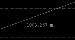
| Surface slope |
Slope: @<SS,LD,P>@ Slope: @<SS,LD,T>@ Slope: @<SS,LD,F>@ |
Slope label: Surface slope, at Leader end point, Units suffix based on project setting Note: The third surface slope option controls how the slope is computed. If you have "@<SS,T,F>@" for the code with the 3rd value as "T", then the true triangle slope is displayed. If value is "F", then the slope is computed in the direction to the text. If you use "F", then as you drag the text around, the slope will change. If "T", the value does not change. |
| Name |
@<NM,O>@ @<OD,O,NSI>@ @<OD,O,NSF>@ @<NM,O>@ @<OD,O,NSI>@ |
Name, from Object Initial surface used to create a cut/fill surface Final surface used to create a cut/fill surface Initial surface used to create a volume grid Final surface used to create a volume grid |
| Layer |
Layer: @<LY,O>@ |
Layer label: Layer, from Object |
| Feature codes |
Feature codes: @<FC,O>@ |
Feature codes label: Feature code, from Object |
| Utilities |
Lines/Pipes
Nodes
|
|
