Interchange Ramp Properties - Direct 90° and Direct 270°
To access intersection ramp properties, click the blue triangle on the ramp alignment to select the Road Ramp, and press F11 to open the Properties pane.
Note: Although you can verify ramp geometry in the Alignment Editor, you should not edit it there; only edit ramp geometry in the Properties pane.
|
Selected Properties for Direct 90° and Direct 270° Ramps
|
|
Synchronization
|
- Ramp pair - If Synchronize (below) = True, this names the ramp that will be synchronized. For direct 90° and 270° ramps, matching is done by finding the tangent point in the middle of the ramp, approximately where the paired ramps are passing each other.
- Synchronize - If false, each ramp computes its own geometry independentlt of the other. If true, the geometry of the two ramps is dependent on each other; if one is changes, the other updates automatically (attempts to acommodate the change). Setting this property for one ramp in a pair, sets it for the other ramp.
- Pair distance - This is the horizontal distance between the alignments at their closest point.
- Joint distance - It is possible to also compute the outer ramp to follow the inner ramp a given distance, a parallel part. In many country this is NOT recommended, actually not allowed at all, but the feature is still in this version, since it can be natural to illustrate an issue etc.
|
|
Horizontal alignment geometry
|
- Horizontal method - Horizontal alignment geometry is computed by either of two basic methods: arcs or spirals. If any segment length is set to 0.0m (line, arc, or spiral segments), the segment is omitted from the calculated alignment.
- Lock main highway - If No, the connection to the main highway is free and will be a result of the property values and the need of length to have a solution. If Yes, the ramp alignment is computed to be locked to a specific station along the highway (Lock length below).
- Lock length - Distance from the point of intersection to the end of the ramp on the main highway's side.
- Connect type - Select whether the connection to the secondary highway is Perpendicular (to this highway) or Parallel (to the other highway).
- Connect deflection angle - The angle of the connection in degrees; positive angles are measured clockwise.
- Connect offset (secondary highway's end) - The distance from the intersection point between the highways along the secondary highway to the perpendicular connection point.
- Line length (secondary highway's end) - The length of the line segment from the perpendicular beginning point.
Horizontal method – Arcs
- Radius (enter) - Beginning radius of the ramp.
- Arc length (enter) - Length of the beginning radius.
- Line length (enter) - Length of the line segment after the beginning radius.
- Main radius - Main radius of the ramp.
- Line length (exit) - Length of the line segment before the ending radius.
- Arc length (exit) - Length of the ending radius.
- Radius (exit) - Ending radius of the ramp.
Horizontal method – Spirals
- Spiral length 1 (enter) - Spiral before beginning radius of the ramp.
- Radius (enter) - Beginning radius of the ramp.
- Arc length (enter) - Length of the beginning radius.
- Spiral length 2 (enter) - Spiral after beginning radius and before the line segment of the ramp.
- Line length (enter) - Length of the line segment after the beginning radius.
- Spiral length 3 (enter) - Spiral after the line segment and before Main radius of the ramp.
- Main radius - Main radius of the ramp.
- Spiral length 3 (exit) - Spiral after Main radius and before the line segment of the ramp.
- Line length (exit) - Length of the line segment before the ending radius.
- Spiral length 2 (exit) - Spiral after the line segment and before ending radius of the ramp.
- Arc length (exit) - Length of the ending radius.
- Radius (exit) - Ending radius of the ramp.
- Spiral length 1 (exit) - Spiral after ending radius of the ramp.
|
|
Deceleration area and Merging area
|
|
Type - Deceleration and merging areas define how ramp geometry splits from/merges onto the highway.
- Default - Uses properties from horizontal alignment geometry to compute the connection from/to the highway. This type also supports all types of Crown locations.
- Fin - This method is specific to the country of Finland. The Crown location is fixed to right side and cannot be changed. In addition, for the Fin type, the Deceleration and Merging sections show these additional properties:
- Taper length - Split length (taper length) at beginning of deceleration area.
- Distance A - Offset value at point A (in the image below).
- Length A-B - Length between point A and B (in the image).
- Distance B - Offset value at point B (in the image).
- Length B-C - Length between point B and C (in the image).
- Distance C - Offset value at point C (in the image).
- Nose length C-D - Nose length between point C and D (in the image).
- Distance D - Offset value at point D (in the image).
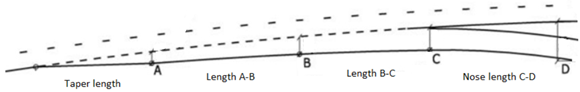
Figure: Ramp deceleration area
|
|
Vertical alignment geometry
|
- Vertical method - Vertical alignment geometry can be computed by any of six basic methods:
S curve
This default method is useful as it always gives an initial result, Then other methods can be used to find an optimal solution to the vertical geometry, as necessary.
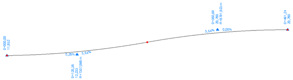
Figure: Vertical ramp geometry with an S curve
User-defined
This method allows you to define the vertical geometry using the properties:
- Relative location - Slides the combination of sag and crest cure along the free vertical length at an interval from 0.0 to 1.0 (if outside the interval, the computation is interrupted).
- Enter radius - The first vertical radius of the curvature. Whether the radius is a sag or a crest depends on whether the gradient is up bound or down bound.
- Exit radius - The last vertical radius of the curvature. Whether the radius is sag or a crest depends on whether the gradient is up bound or down bound. This radius is always the opposite of the Enter radius (sag and crest).
- Gradient - The maximum grade of the curvature, given in %.
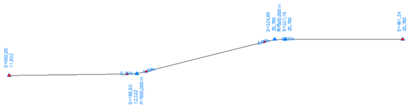
Figure: User-defined vertical ramp geometry
Minimum radius
This method computes using the minimum radius as input. Other values are the same as for the User-defined method.
- Relative location - Slides the combination of sag and crest cure along the free vertical length at an interval from 0.0 to 1.0 (if outside the interval, the computation is interrupted).
- Gradient - This defines the maximum grade of the curvature in %.
- Minimum sag radius - This is used as the radius at the sag curve.
- Minimum crest radius - This is used as the radius at the crest curve.
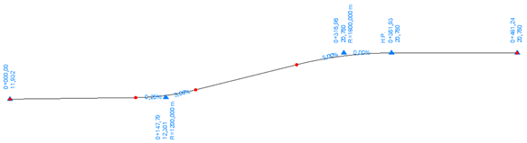
Figure: Minimum radius ramp vertical geometry
Maximum grade
This method computes using the maximum grade as input (GradeMax is used as the grade value and is not changeable). Other values are the same as for the User-defined method.
- Relative location - Slides the combination of sag and crest cure along the free vertical length at an interval from 0.0 to 1.0 (if outside the interval, the computation is interrupted).
- Enter radius - The first vertical radius of the curvature. Whether the radius is sag or a crest depends on the whether the gradient is up bound or down bound.
- Exit radius - The last vertical radius of the curvature. Whether the radius is sag or a crest, depends on whether the gradient is up bound or down bound. This radius is always the opposite of the Enter radius (sag and crest).
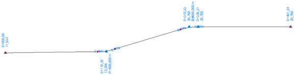
Figure: Maximum grade ramp vertical geometry
Min radius - Max grade
This method computes using both the minimum radius (minimum sag radius and minimum crest radius) and maximum grade as inputs. Maximum grade is used as grade value. Minimum sag radius is used as the radius at the sag curve. Minumum crest radius is used as the radius at the crest curve. Other values are the same as for the User-defined method.
- Relative location - Slides the combination of sag and crest cure along the free vertical lengthat an interval from 0.0 to 1.0 (if outside the interval, the computation is interrupted).
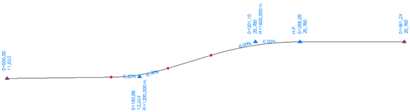
Figure: Vertical ramp geometry with minimim radius - maximum grade
Two PI
The first vertical radius of the curvature. Whether the radius is sag or a crest depends on whether the gradient is up bound or down bound.
- Enter radius - The first vertical radius of the curvature. Whether the radius is sag or a crest depends on whether the gradient is up bound or down bound.
- Exit radius - The last vertical radius of the curvature. Whether the radius is sag or a crest, depends on whether the gradient is up bound or down bound. This radius is always the opposite of the Enter radius (sag and crest).
- Enter distance - The extended distance from beginning point where the vertical alignment starts. VPI is computed by this value and used to find the sag/crest curve. If a 0.0 value is given, the distance is automatic calculated to be 1/5 of the total length.
- Exit distance - The extended distance from ending point (measured backwards) where the vertical alignment ends. VPI is computed by this value and used to find the sag/crest curve. If a 0.0 value is given,, the distance is automatic calculated to be 1/5 of the total length.
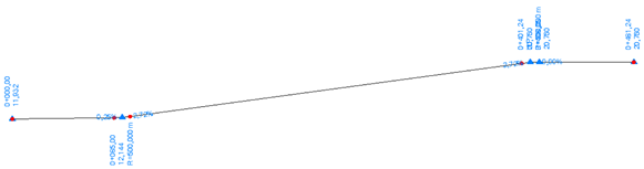
Figure: Vertical ramp geometry with two PIs
Read-only Properties
In all different vertical methods, some properties are just for viewing. They are not editable, but is important to give the user information about restrictions and limits in how to design the vertical alignment. These properties are grayed out, just to show they are not possible to edit. Normally, they are derived from higher leveled properties, like Design speed etc.
- GradeMax - Maximum accepted grade value at the ramp. This value is pre-defined, but will be possible to edit in Project Setting in later versions. Grade max value is related to Design Speed major property. This property is not editable, therefore it is colored gray.
- RadiusMinSag - Minimum accepted radius at sag (valley) curve. Like GradeMax it is a pre-defined property. It is not editable, therefore it is colored gray.
- RadiusMinCrest - Minimum accepted radius at crest curve. Like GradeMax and RadiusMinSag it is a pre-defined property. It is not editable, therefore it is colored gray.
|
|
Derived geometry
|
|
In addition to computed ramp alignment, derived geometry is also supported.
- Road edge, outside
- Road shoulder, outside
- Road edge, inside (if needed)
- Road shoulder, inside
- Length split (enter) - The distance at which the lane splits from the basic road leg lane at the access piece. The split can be computed using one of three different methods (see Split method (enter) below).
- Split method (enter/exit) - The method used at the access part of the ramp:
- None - (right turn starts with full lane width).
- Length parallel (enter) - The length of the lane where the access lane width is constant.
- Length widening (enter) - The width of the lane in the curve is normally wider than at the access (and exit) part. To change the wide out of the lane into the curve, it starts at beginning point of the curvature (where the parallel part ends), in order to handle the change of width over some distance.
- Lane width (enter) - The width of the lane (access part of right turn).
- Lane slope (enter) - The % slope of the lane (access part of right turn).
- Lane width (center) - The width of the lane in the curve area.
- Lane slope (center) - The % slope of the lane in the curve area.
- Shoulder width - The width of the shoulder in whole area.
- Shoulder slope - The % slope of the shoulder in the curve area.
- Length widening (exit) - The width of the lane in the curve is normally wider than at the exit (and similar to the access) part. To change the wide out from the curve and into the exit area it is handle over this length distance.
- Length parallel (exit) - The length of the lane where the exit lane width is constant.
- Length split (exit) - The length where the lane is split from basic road leg lane at the exit part. The split can be computed by three different methods (see Split method (exit) above).
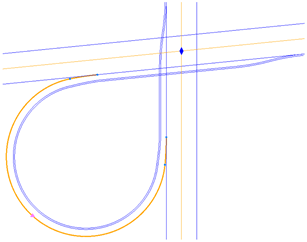
Figure: Direct 270° ramp with derived geometry
|
|
Merging area
|
- Distance A - Offset value at point A (see Illustration Merging area).
- Nose length A-B - Nose length between point A and B.
- Distance B - Offset value at point B (see Illustration Merging area).
- Length B-C - Length between point B and C.
- Distance C - Offset value at point C (see Illustration Merging area).
- Length C-D - Length between point C and D.
- Distance D - Offset value at point D (see Illustration Merging area).
- End taper length - Split length (end taper length) at end of merging area.
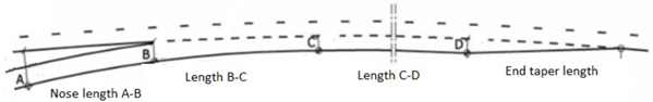
Figure: Ramp merging area
|
Related topics
Interchange Ramp Properties - 0° On- and Off- (S shaped)
Interchange Ramp Properties - 180° On- and Off- (D shaped)
Create and Edit a Corridor Intersection
Copy and Paste Corridor Interchange, Intersection, and Cul-de-Sac Properties
Save a Corridor Intersection Template
Load a Corridor Intersection Template
