Create and Edit a Corridor Intersection
Use the Create Intersection command to create parametric geometry for the junction between two or more alignments or corridors. Then you can control the shape of the intersection using properties for the various lines used to form the intersection.
Tip: The best way to learn how to create an intersection is to create a simple example and then modify and see what changes when they are updated.
Prerequisites:
- Licensed module; See the Subscription Plans page. For a license matrix by command, see the License page in the TBC Community. Also see View and manage licensed features.
- Two or more alignments that intersect
or
- Two or more corridors that intersect (the template instructions must have lane properties)
Before you create intersections:
- Select Project Settings in the Quick Access Toolbar.
- Review and modify as needed:
- Units > Station
- View > Corridor Template View
- View > Station Navigation
- View > Superelevation Diagram
- Computations > Road Intersection
- Computations > Corridor
- Click OK.
To access the command:
- Select Create Intersection in Corridors > Infrastructure.
- Press [Control], select two corridors or two alignments, right-click and select Create Intersection.
To create an intersection:
- From the Included alignments or corridors box, pick either the alignments or corridors between which you want to create an intersection.
If there is more than one possible intersection location, select the location you want. The marker for the intersection point you choose will be highlighted.
- In the Name box, type a unique name as you want it to appear in the Project Explorer and Selection Explorer.
- To create a roundabout rather than a T-, X-, or Y- intersection, check the Create roundabout box.
- To use parameters from a previously saved intersection template, check the Load properties from template box.
By default, the Intersection template list is populated with names of files in this folder: C:\ProgramData\Trimble\IntersectionTemplates
Select a template in the list or click the Browse button, browse to the template file, and click Open.
- Click Apply and Close when you are done.
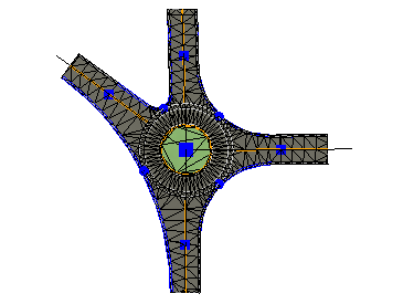
The intersection is created and appears in graphic views, and the Project Explorer. The intersection point is represented by a magenta square marker. The legs are represented by blue square markers, and the connections are represented by blue round markers. In addition, a surface is created with the same name as the intersection.
To edit an intersection:
- Right-click the intersection, a leg, or a connection in the Project Explorer and select Properties (or press [F11]).
- Edit any of the parameters that control the size and shape of the intersection, leg, connection, island, or interpolation line:
- Intersection Properties
- Leg Properties
- Connection Properties
- Turn Lane Properties
- Island Properties
- Interpolation Line Properties
- Twin Intersection Joint Properties
Tip: To modify common properties for multiple parts of an intersection, right-click an intersection, and choose Select Child Lines from the context menu.
Here are other tools that can help you review and edit your intersection objects:
- Enable grips to see the ends of line segments. See Startup and Display Options.
- Enable linemarking to see locations and elevations of vertical points and the radii radius vertical arcs. See View Settings.
- Edit linestrings to see their details. See Edit a Linestring's Horizontal Segments.
- Explore objects to see elevation at any position. See Explore an Object.
- Use the Profile Viewer with Explore Object to track lines in Plan and Profile Views. See View Linestrings in Profile.
- Use the 3D View to get a better picture of the results.
Dependencies:
- The corridor does not reference the intersection, but the intersection is dependent upon the corridors that connect to it. If any of the corridors change, the intersection updates in response. The resulting surface is dependent upon both the corridors and intersection, and updates when any of them change.
