Cul-de-Sac Properties
Use these properties to control the shape of roundabout and turning hammer cul-de-sacs.
Note: This topic describes just the more important, confusing, or complex properties.
|
Selected Cul-de-Sac Properties (Roundabout) |
|
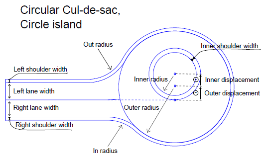
| Circular cul-de-sac |
Rebuild method:
|
| Main leg |
Minimize leg - As a standard definition, the road leg is minimized automatically (Yes). This option computes the shortest necessary length to the current leg. The minimized length will change depending on the other properties given to this leg. If No is selected, another property is shown:
Vertical adjustment method - Select a method for vertical adjustment of the road leg alignment:
Vertical adjustment length - This shows the distance from the connection to the main road lane outbound along the leg. |
| Tilting |
Note: For more on roundabout tilt properties, see Intersection Properties. Tilting - Automatic is the default, which means that the roundabout outer radius is tilted according to the legs of the intersection. If there are 3 legs, the tilting will be exactly matching to the elevation of the 3 legs. If there are more than 3 legs, the match will be optimized (least square best match). Then the inner radius of the roundabout will be "back calculated", meaning that the vertical alignment will be found by the slope of the roundabout lane. In this way, the slope of the lane will be correct if it is computed by difference of elevation between inner and outer radius of the roundabout (perpendicular to inner radius alignment).
Tilting
Slope - This shows either the automatically calculated or user-defined slope of the entire roundabout. Tilt direction - This shows the bearing of the high side of the tilt, which you can control if the tilt is user-defined. The zero (0) bearing is north, and bearings are measured clockwise. Vertical offset inner shoulder - Specify this vertical delta between inner shoulder and inner circle when using the User-defined tilt all circles tilt method described above. Vertical offset inner circle - Specify this vertical delta between inner shoulder and inner circle when using the User-defined tilt all circles tilt method described above. Delta elevation, Leg < > - For a user-defined tilt, this shows the deviation between the automatically calculated tilt and the one you have specified. Slope - This shows either the automatically calculated or user-defined slope of the entire roundabout. Tilt direction - This shows the bearing of the high side of the tilt, which you can control if the tilt is user-defined. The zero (0) bearing is north, and bearings are measured clockwise. Delta elevation, Leg < > - For a user-defined tilt, this shows the deviation between the automatically calculated tilt and the one you have specified. |
| Roundabout |
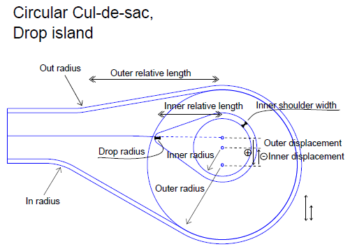
Island type - Select either a circular or tear-drop shape for the center island of the roundabout. There are additional properties for the Drop shape. Drop radius (not available for Circle islands) - Outer relative length (not available for Circle islands) - Inner relative length (not available for Circle islands) -
In/out vertical turning method - This shows the method used to compute the vertical connection between two legs. The vertical curve is limited to the horizontal length of the corresponding curvature. There are two methods:
In radius - This is the access radius that is used in the horizontal methods. Incoming horizontal turning method - This is the access method used in the horizontal method. Incoming vertical turning method - This is the access method used in the vertical method. Out radius - This is the exit radius that is used in the horizontal methods. < > lane width - This shows the distance between the inner circle (radius above) and outer circle. This value is constant all the way around the roundabout. Lane slope - This shows the slope of roundabout lane. A negative value means that the lane slopes down in the outbound direction. This value is constant all the way around the roundabout. Note: If your intersection connects to a corridor that defines lanes (using instructions tagged with the Lane edge code), the Lane width and Lane slope properties do not appear here; these properties are controlled by the parameters in the corridor template instructions. See Create Corridor Template Instructions for more information. < > shoulder width - This shows the width of the road's shoulder (distance between the outer circle and outer shoulder edge). < > shoulder slope - This shows the slope of the road's shoulder. A negative value means that the shoulder slopes down in the outbound direction. Curb height - This shows the vertical distance from the flow line to the top of curb. |
|
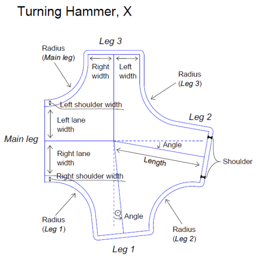
Selected Cul-de-Sac Properties (Turning Hammer) |
|
| Road Intersection |
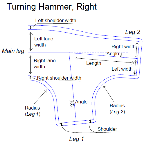
Rebuild method - See description above. Parent corridor for the masses - When you calculate material volumes for a corridor, it will include the volumes for the connected cul-de-sac if you select the associated corridor here. Type of turning hammer - Select Center, Left, Right, or X to mirror the real-world or design layout.
vertical turning method - This shows the method used to compute the vertical connection between two legs. The vertical curve is limited to the horizontal length of the corresponding curvature. There are two methods:
Minimize leg - As a standard definition, the road leg is minimized automatically (Yes). This option computes the shortest necessary length to the current leg. The minimized length will change depending on the other properties given to this leg. If No is selected, another property is shown:
|
| Main leg |
< > lane width - This shows the distance between the inner circle (radius above) and outer circle. This value is constant all the way around the roundabout. < > lane slope - This shows the slope of roundabout lane. A negative value means that the lane slopes down in outbound direction. This value is constant all the way around the roundabout. < > shoulder width - This shows the width of the road's shoulder. < > shoulder slope - This shows the slope of the road's shoulder. A negative value means that the shoulder slopes down from the centerline. Note: If your intersection connects to a corridor that defines lanes (using instructions tagged with the Lane edge code), the Lane width and Lane slope properties do not appear here; these properties are controlled by the parameters in the corridor template instructions. See Create Corridor Template Instructions for more information. |
| Virtual leg 1 |
Length - This shows the length of the calculated leg, starting from the end of the alignment.
< > lane width - See Main leg above. < > lane slope - See Main leg above. Radius - Angle - Shoulder - Shoulder slope - See Main leg above. |
| Virtual leg 2, 3 |
See Virtual leg 1 above. |
|
Selected Cul-de-Sac Properties (Turning Hammer) |
|
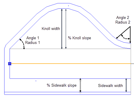
| Side Sidewalk width Sidewalk slope Knoll width Knoll slope Angle 1 Radius 1 Angle 2 Radius 2 |
Left/Right - Specify the side of the road on which to add the knoll (bulge, "beer belly").
|