Intersection Properties
|
Selected Intersection Properties |
|
| Road Intersection |
Rebuild method - Auto is the default setting that allows the intersection and corresponding surface to rebuild automatically after each change that affects it. Select Show empty to hide the surface in graphic views while you make edits. The surface cannot be automatically or manually rebuild in this state. Select By user to suspend the process of rebuilding the intersection and surface until you select Rebuild Intersection. Type - The options K, Y, T, or O depend on the number of intersecting legs. Parent corridor for the masses - When you calculate material volumes for a corridor, it will include the volumes for the connected intersection if you select the associated corridor here. State - In some situations, intersections can be defined from more than one intersection point. The read-only definition used is shown here (e.g., Valid (multiple point)). Vertical adjustment - Select Yes to automatically adjust the vertical geometry of secondary road/roundabout legs so that they follow a certain rule when joining to the main road/roundabout’s central island. Interpolation method - Shows the method used to add interpolation lines when forming the surface:
Main road method
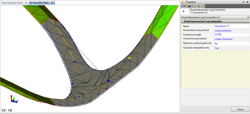
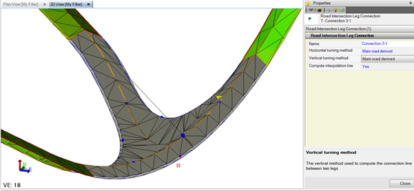
In addition, when there is T-intersection, the connection 3-1 in T is the main road edge. There is a new method "Main road derived". In this option, the connection 3-1 is not computed using a connection method, but the main road edge is taken as it is (derived or s-curve) to use in connection. Note: If the chosen main road method is "Derived", then always the "Main road derived" in T-intersection's connection 3-1 must be used. When Horizontal turning method is "Main road derived", then the vertical method is the same as well.
|
| Roundabout
(roundabouts only) |
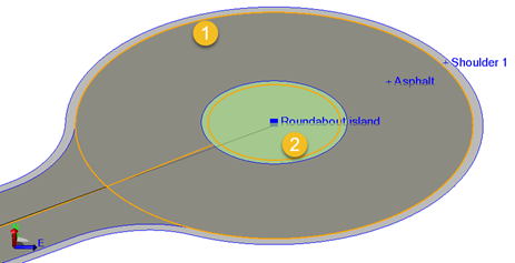
Style - Circular is the default for round islands. Select Non-circular for oval islands. Then adjust the two different radii below. Radius - Use this to control the size of the inner circle/center island. The overall size of the intersection is impacted by this, as the lane and shoulder width stay the same. Radius 2 - For non-circular roundabouts, there are two radius boxes. This shows the long radius to the inner circle of the roundabout. Direction - For non-circular roundabouts, this is the direction between the two focal points of the roundabout. The roundabout can be rotated by changing this value. Focal point distance - This shows the distance between the two focal points of the non-circular roundabout. Lane width - This shows the distance between the inner circle (radius above) and outer circle. This value is constant all the way around the roundabout.
Note: If your intersection connects to a corridor that defines lanes (using instructions tagged with the Lane edge code), the Lane width and Lane slope properties do not appear here; these properties are controlled by the parameters in the corridor template instructions. See Create Corridor Template Instructions for more information. Lane slope - This shows (or lets you specify) the slope of roundabout lanes. A negative value means that the lane slopes down in outbound direction. This value is constant all the way around the roundabout. Width of inner shoulder - This shows the distance from the inner circle to the inner area line (shoulder of the inner circle). This width is part of the total lane width. Slope of inner shoulder - This shows (or lets you specify) the slope of the inside shoulder of a roundabut. The default value is the same as the Lane slope above. A negative value means that the shoulder slopes down in outbound direction. This value is constant all the way around the roundabout. Width of outer shoulder - This shows distance from the outer radius to the outer area line (shoulder of the outer circle). This width is part of the total lane width. Curb height - This shows the vertical distance from the flow line to the top of curb. |
| Tilting
(roundabouts only) |
Tilting
When using either of these tilting methods:
the inner shoulder and inner circle should be elevated based on the tilted surface (plane). To do so, these two parameters are required:
The lane and inner shoulder will still have varying slopes all the way around, but with different offsets from the base plane.
Slope - This shows either the automatically calculated or user-defined slope of the entire roundabout. Tilt direction - This shows the bearing of the high side of the tilt, which you can control if the tilt is user-defined. The zero (0) bearing is north, and bearings are measured clockwise. Vertical offset inner shoulder - Specify this vertical delta between inner shoulder and inner circle when using the User-defined tilt all circles tilt method described above. Vertical offset inner circle - Specify this vertical delta between inner shoulder and inner circle when using the User-defined tilt all circles tilt method described above. Delta elevation, Leg < > - For a user-defined tilt, this shows the deviation between the automatically calculated tilt and the one you have specified. |
| Roundabout center point
(roundabouts only) |
Easting, Northing - This shows the 3D coordinate of the roundabout's center island. Normally this will be the intersection point where the alignments/corridors converge. The center point can be moved slightly off center, but if the point specified is too far away from the actual center, the intersection cannot be updated. By moving this point, the roundabout may appear eccentric according to the intersection point of the alignments/corridors. Elevation - This shows the mean elevation of the intersection point. Normally this will be the mean value of the alignment elevations at the point. This value can be changed, which will lift up or drop down the whole roundabout. |
|
Selected Road Intersection Leg Connection Properties |
|
| Road intersection leg connection |
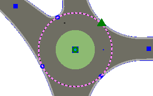
Main horizontal turning method - This method is called 'Touch roundabout double radius'. It computes a tangent point to the outer radius of the roundabout by using the two radii values R1-R2 (Turn radius 1 – Turn radius 2). Turn radius 1 - The first of the two radii. The value of this radius is the smallest, normally around 15.0 m. Turn radius 2 - The second of the two radii. The value of this radius is the largest, normally in the interval from 50-100.0 m. Main vertical turning method - The vertical method is called 'Copy'. The method connects the vertical alignment to the elevation of the outer roundabout at the tangent point. No other methods are available in this case. |
