Edit a Linestring's Horizontal Segments
The linestring editing command provides one familiar tool with which you can edit a large array of imported CAD lines of many types, such as polylines, arcs, and splines, automatically converting them in the process to linestrings, and enriching them as needed with geometric attributes not otherwise supported by the source objects.
Edit linestrings by redefining their points and the connections (segments) between the points, as well as by adding, inserting, and deleting segments. When you are editing a linestring, the active segment's start point, end points, and direction are indicated in the Plan View. The active segment is also highlighted in the 3D View. You can pick linestring segments and vertical points of intersection (VPIs) in the 3D View.
To define vertical points of intersection (independent of the segment end points) at specific distances along the linestring, add vertical control points using the operations in Edit a Linestring's Vertical Control Points.
|
|
|
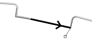
The current segment, end point, and direction of the linestring are indicated during editing. An X indicates the linestring's start point. |
Notes:
- You can use any of the various Snap Mode Options when picking points to create your line segment, including snap options that allow you to create a new line segment that is orthogonal to either the axis or the previous line segment.
- See Horizontal Linestring Segment Options for a description of each of the options available to create and edit horizontal linestring segments.
To access these options:
If you have just created a linestring, skip to one of the operations below. Otherwise, select a line or linestring and do one of the following:
- Select Edit Linestring.
- Click the Edit icon on the Properties pane toolbar when a linestring is selected.
- Right-click, and select Edit from the context menu.
The Edit Linestring command pane displays. Click the Horizontal tab.
To view and select each horizontal segment in sequence:
- Click the back and forward arrows on either side of the Current segment list, or move your cursor along the linestring in a graphic view and click to select the segment.
To add a straight segment:
- In the Segment group's Type box, select Straight.
- Follow the steps in To specify a segment's end (or start) point below.
- Click or press . The segment is saved and you are prompted to specify the end point for the next segment.
To add a curved segment:
- In the Segment group's Type list, select one of the following options:
- Smooth Curve - Select this option to create a smooth, spline-curved segment that extends from the previous segment's endpoint (or the line's start point), through an intermediate point on the curve, to a specified segment endpoint.
- Best Fit Arc - Select this option to create a curved segment that extends from the previous segment's endpoint (or the line's start point), through or near one or more intermediate points, to a specified segment endpoint based on a best fit radius point.
- Arc - Select this option to create a curved segment that extends from the previous segment's end point,. or the line's start point to the new segment's end point based on the radius, direction, and size you specify.
- Tangent Arc - Select this option to create a curved segment that extends from the previous segment's endpoint to the new segment's endpoint based on the specified Input method:
- Begin tangent (coordinate) - Specify a coordinate to create an arc segment that is tangent to the previous segment. If there is no previous segment, a straight segment will be created. Repeat using this option to create an arc segment that is tangent to the straight segment.
- Begin tangent (bearing and arc length) - Specify the bearing, arc length, and elevation for the arc segment.
- Begin tangent (radius and arc length) - Specify the radius, arc length, direction, and elevation for the arc segment.
- Begin tangent (delta angle and arc length) - Specify the delta angle, arc length, direction, and elevation for the arc segment..
- End tangent - Specify a coordinate to create an arc segment that is tangent to the segment that follows it.
- Tangent tangent - Specify a coordinate to create an arc segment that is tangent to both the segment that precedes it and the segment that follows it. Note that the length of either the preceding or the following segment will be altered as necessary to facilitate the tangent-to-tangent arc.
- PI Arc - Select this option to create an arc based on the point of intersection (PI) between two segments. For the first segment that specifies the PI, select PI-Arc in the Segment Type list. Enter a radius and the coordinate (or point ID) of the PI. Based on the radius, this first segment will include a straight portion tangent to the arc and then the arc. If the radius is too large, the entire segment will be an arc. Then specify the next segment from the PI as usual.
- Follow the steps in To specify a segment's end (or start) point to specify the end point of the curved segment.
To add a straight segment at a deflection angle from the preceding segment:
- In the Segment group's Type list, select Deflection.
- For the Direction, select the perpendicular left (-90 °), perpendicular right (90 °), straight ahead (0 °) deflection angle option, or select Specified angle to enter a specific deflection angle.
Note: Positive deflection angles are measured clockwise from the direction of the previous segment.
- Pick a point in the graphic view to specify the length, or type a value in the Length box.
- Type an elevation for the end point in the Elevation box, and click or press .
To specify a segment's end (or start) point:
- In the End Point (or Start Point) group's Type list, select Coordinate or Point ID.
- Depending on the type you selected, click in either the Coordinate box or the Point ID box.
- For a coordinate, pick a location in a graphic view, type a coordinate, or right-click for COGO coordinate options. Then enter the elevation for the starting point in the Elevation box, or right-click for COGO elevation options.
Note: If desired, click the
 icon to toggle the auto-advance mode on. When the icon looks like this
  , the elevation value you entered will be held and this box will be skipped when creating additional segment end points.
Tip: You can toggle the Auto-advance mode on/off by pressing [Control] + [.] (period or decimal point). - For a point ID, pick a named point (point with an ID) in a graphic view or type a point ID. The elevation of the point you specified (if defined) is automatically used to establish a vertical point of intersection on the line at that point.
- Click .
Note: If a linestring includes vertical control points (VPIs), and you edit the linestring's horizontal segments, the VPIs may or may not retain their original stations on the linestring. For details, see the Scenarios section at the bottom of this topic.
To edit a segment:
- Select the segment by picking it in the plan view, selecting it in the Current segment list, or clicking the Browse button and selecting it in the Browse Horizontal Segments list.
- Modify any of the options for the segment, and click .
To remove a segment:
- Select the segment by picking it in the plan view, selecting it in the Current segment list, or clicking the Browse button and selecting it in the Browse Horizontal Segments list.
- Click the
 icon. The segment and its end point are removed, and the adjoining segments' end points are joined.
Note: To delete a segment without joining the adjoining segments, use the Delete Line Segment command.
To insert a segment before the current segment:
- Select the segment before which you want to insert a new segment by picking it in the plan view, selecting it in the Current segment list, or clicking the Browse button and selecting it in the Browse Horizontal Segments list.
- Click the
 icon.
icon. - Follow the steps in To specify a segment's end (or start) point above to specify the new segment's end point, which becomes the new location of the start point for the segment you selected. The new segment is inserted before the selected segment.
To insert a new first segment:
- Select the linestrings 'start' coordinate or point by picking it in the plan view or selecting it in the Current segment list.
- Click the icon.
- Follow the steps in To specify a segment's end (or start) point above to specify the start point for the new, first segment in the linestring.
To add a segment onto the end:
- Select the last segment by picking it in the plan view or selecting it in the Current segment list.
- Click the
 icon.
icon. - Follow the steps in one of the To add a * segment operations above.
To view and select a segment in a list:
- Click the Browse button. The Browse Horizontal Segments dialog displays.
- Select the segment you need, and click .
To reverse the segment order/switch the linestring's start and end points:
- Click the
 icon on the pane's toolbar. You can confirm the order by moving your cursor along the linestring in the graphic view. The direction of the linestring is shown in the plan view an arrow on the selected segment.
Scenarios:
Click here for descriptions of what happens to vertical points of intersection (VPIs) when you add, move, or change horizontal segments.
