Understanding Corridor Intersections and Cul-de-Sacs
Corridor intersection and cul-de-sac functionality in Trimble Business Center enables you to create common cross-roads and junctions, such as simple, single-level roundabouts, and T-, Y-, and X-intersections that connect to corridors in your model. You can also create more complex interchanges, as well as hammer and roundabout cul-de-sacs (with a separate command).
Note: There are other types of corridors (e.g., canals and railways), but the features described here are intended for modeling roadway corridors.
The foundation of intersections and cul-de-sacs consists of 3D lines that are used to calculate surface models. The internal, geometric position of each line corresponds to the other lines in the intersection or cul-de-sac. When an intersection or cul-de-sac property is changed, the geometry is recalculated to update all of the child lines in the intersection/cul-de-sac. This is done in 2 steps:
- The program computes all of the linework in 3D.
- The program generates a surface model from the linework (this can be turned on/off).
Intersections
A roundabout can be intersected by up to six legs, which are the incoming alignments or corridors. T- and Y-intersections each have three legs, and X-intersections have four legs.
Cul-de-Sacs
A cul-de-sac intersection is normally placed at the end of a street. This type of intersection normally consists of one leg, but can be formed as a 'turning hammer' with two or three legs.
Road network topology
To define a corridor intersection, you must select either two or more alignments or two or more alignment-based corridors. The selected objects are validated against each other to find the 3D points (X, Y, and Z/elevation) where they match/can intersect. The network of converging lines may produce many possible intersection points, in which case you must select which point to use in computing the intersection (as well as the type of intersection). Depending on the number of legs, only certain types of intersections can be selected. Each part of an intersection is shown in the Project Explorer and can be selected so that you can edit their properties.
Input
You can create intersections based on two types of objects
- Alignments (horizontal and vertical)
or
- Corridors (where alignments are part of the corridor data)
The alignments (whether alone or embedded in corridors) must also form a network network topology by having valid points where the alignments can connect. A valid intersection requires that the difference in elevation of intersecting points is within a maximum accepted value (to be computable).
Output
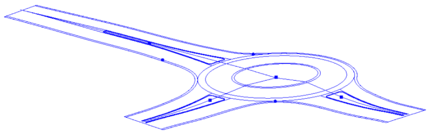
The primary output of an intersection computation is 3D line work describing all breaklines in the model. All of this linework is separated into four groups:
- Inner island lines (curb lines describing island geometry)
- Inner shoulder lines (all lines on the inside of lanes at every leg)
- Road edge lines
- Road shoulder lines
For roundabouts, there are also inner/outer, central island lines. There may also be subordinate lines that help to create the surface model.
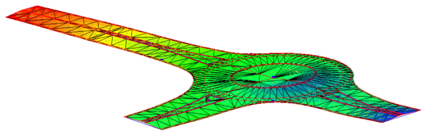
The secondary output is a surface model created from the breaklines of the road intersection object. This surface has the same name as the intersection.
Connections to corridors
When you create a corridor that you plan to connect to one or more intersections and/or cul-de-sacs, you must select lane properties in the Type of code above list:
- Undefined - This is the default for instructions that do not need to connect to and help in the formation of an adjoining intersection or to identify an area between lanes as a median (see note below).
Note: If your corridor contains a center median (denoted by instructions tagged as Undefined) between lanes (instructions tagged as Lane edge; see below) the median continues into any adjoining road intersection. How you define the height and width of the median and lanes in the corridor instructions specifies how they are formed in the intersection. Intersection properties dictate how long the median is/where it ends.
- Lane edge - Select this for an instruction that ends with an edge of pavement (EoP) node. It can then be used to connect to a corresponding lane edge node automatically generated in an intersection or cul-de-sac.
Note: If your corridor contains one or more lanes (denoted by instructions tagged as Lane edge) the lanes continue into any adjoining road intersection. No new lane properties are added to the road intersection, but the intersection surface is formed with lane lines (breaklines). When lanes are projected into an intersection, the Lane width propety is no longer displayed in the Properties pane; the width is defined by the corridor's template instruction.
- Shoulder - Select this for an instruction that ends with an edge of shoulder node. It can then be used to connect to a corresponding shoulder node automatically generated in an intersection or cul-de-sac.
These types of lane codes are available when you create Offset/Slope Instructions or Offset/Elevation Instructions.
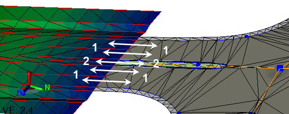
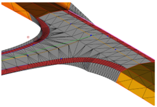
- Two lanes on either side of the corridor form lanes in the intersection
- A center median in the corridor surface forms a center median in the intersection
Figure: Median and lanes in a corridor surface and an adjoining intersection surface
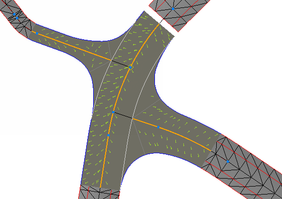
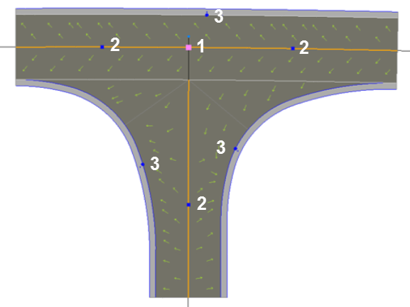
Markers
- The intersection point is represented by a square, magenta marker.
- Legs are represented by square, blue markers.
- Connections are represented by round, blue markers.
Volume calculations
Using average end area calculations is not an accurate way to compute volumes through an intersection. Where corridors connect to an intersection, the corridors are "trimmed back" so that they stop where the intersection starts. The subgrade surface that is created is used to calculate the volumes for the intersection. In the Corridor Earthwork Report, the intersection is calculated as a site; the import and export amounts are added to the corridor volume calculations. The report includes the amount of cut/fill for the intersection, but does not report the materials used or the volumes by strata.