Display Options
Set Startup and Display options to specify program-wide preferences for application startup behavior and graphics display.
To access these settings:
- Select Options. The Options dialog displays.
- Click Display in the left pane.
The following options are available:
|
Options |
|
|
Graphics Window Options |
|
| Display data tips |
Check this box to display more detailed information when you hover over objects in a graphic view. Note: This may conflict with the data list that appears when you graphically select an area with multiple objects. |
| Background color |
Click an option to set the color of the background used in the graphics views. If you select Custom, you'll have the option to choose a background color. Tip: You can also click the Toggle Background Color icon on the Status Bar to quickly invert the background color (black or white) for all graphic views. |
| Highlight color |
Click Browse button to specify the color to display objects in when they are selected. |
| Cursor color |
Click Browse button to specify the color of the cursor so they are visible when shown over a PDF or an image. |
| Line marking color |
Click Browse button to specify the color of line markers and labels so they are visible when shown over an image or surface. |
| Pick aperture pixels |
Enter a size (in pixels per side) for the box displayed on the selection (pick) cursor used in graphic views. |
| Highlight line width |
Specify the width to display lines in when they are selected. |
| Reverse zoom mouse wheel |
De-select this check box to specify that the mouse wheel causes the graphic view to zoom in when you rotate the wheel away from you, and zoom out when you rotate the wheel toward you. Select this check box to specify that the mouse wheel causes the graphic view to zoom out when you rotate the wheel away from you, and zoom in when you rotate the wheel toward you. |
| Limit rotation in 3D View |
Select this check box to prevent objects in the 3D View from being rotated upside down. |
| Enhance surface visualization in Plan View |
De-select this check box to specify that all surface objects in the Plan View display at an elevation of zero (0.0), which hides any surface shadows and provides faster performance. (No elevations are actually changed.) Select this check box to specify that all surface objects in the Plan View display at their true elevation, which results in the display of surface shadows for better surface visualization. Note: Projected surfaces displayed in the Cutting Plane View are always displayed in an enhanced mode regardless of this setting. |
| Turn on CAD grips |
Check this check box to display CAD grips on linestrings, polylines, rectangles, circles, arcs, labels, and text in the Plan View that enable you to move and modify the objects quickly and easily using just your mouse. |
| Adjacent segments |
If Turn on CAD grips is checked, enter the number of adjacent line segments on each side of the selected segment for which you also want to display grips. |
| Display visual snap indicators |
Check this check box to display snap point visual indicators in the various 2D graphic views, making it easier to select snap points in existing geometry when using running snaps to create CAD objects. |
| Include elevation in selected entities list |
Check this check box to include the elevation for each CAD object/entity when your initial selection in a graphic view displays multiple objects in a selection list. This enables you to more easily discern and select the one you want (for example, for snapping or exporting). |
| Rotate and zoom around center point in 3D view |
Check this check box to specify that the center point in a 3D view be used for rotation and zooming. |
| Z axis always up for 3D View rotation |
By default, you are restricted to rotating around the Z axis and X axis with the Z axis pointed up in 3D views. This constraint can be useful in keeping the view manageable. However, if you require the ability to perform a free rotation in which the Z axis can point in any direction (for example, to verify scan registration results), you can deselect this check box. In addition, you can toggle the Z Axis Always Up state off and on using either of the following:
|
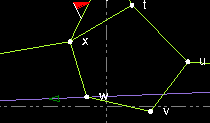
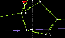
| Show direction arrows for observations |
Check this check box to specify that directional arrows be displayed with observations in graphic views. Without direction arrows:
With direction arrows:
|
| Use double-precision patches |
Check this check box to specify that a 64-bit number be used to store and manipulate surface verticies. This option can be helpful in special cases when you are working with very large surface sizes or require extremely high precision. If unchecked (default), single-precision is applied using 32-bit numbers to store and manipulate surface verticies. This option requires half the computer memory of the double-precision option with some loss of precision. Either option should work fine for almost all projects. |
| Select polygons by edges only |
Check this check box to specify that a polygon can be selected only by clicking any of the linestrings that define it's edges. If unchecked, you can also click inside the polygon to select it. |
| Use large icons for Quick Access Toolbar |
Check this check box to double the size of the icons on the Quick Access Toolbar (which appears above the ribbon by default) and in the Project Explorer. Note: To see the changes, you will need to save your work, close and re-open the program. |
| Advanced |
Click this button to display the Advanced Graphics Options dialog. |
|
Fonts |
|
| Gridline and scalebar labels | |
| Object labels |
Specify the typeface to use for gridline and scalebar text. |
| CAD text (failsafe) |
Specify the typeface to use for CAD text objects that reference a font that is either not included in the imported font's definition or unrecognized by your operating system. |
|
Theme |
|
| Light / Dark |
Select Light or Dark theme from the drop-down list. The default is light. The changes are applied automatically after you click OK. Note: If you export a project that uses the Dark theme and then import that project into TBC version 2025.20 or lower, the screens will be functional but not legible. To fix this, click Options > Manage Options > Restore Defaults, or import a project that does not use the Dark theme. |