Extract Cross-Sections from a Point Cloud
Use the Extract Cross-Sections from a Point Cloud command to create open or closed 3D cross-section line segments from a point cloud based on any of the following:
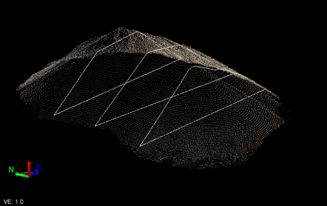
- Two scan points - Select start and end scan points to create a line and extract a single cross-section along the line (for example, creating a contour line along a stockpile).
- Reference lines - Select one or more linear objects (such as linestrings or CAD lines) to extract one or more cross-sections along the lines (for example, extracting underground mine profiles along predefined drilling/excavation reference lines).
- An alignment - Select an alignment or other linear object (such as a linestring) and specify the intervals and offsets to use to extract one or more cross-sections perpendicular to the alignment or line (for example, extracting cross-sections along an alignment of a scanned roadway).
Prerequisites:
- See the Subscription Plans page. For a license matrix by command, see the License page in the TBC Community. Also see View and manage licensed features.
- This command assumes that the point cloud represents the surface of an object (for example ground or tunnel); therefore, it is highly recommended that you classify the point cloud and make unnecessary points invisible in advance. Unfiltered point cloud points can compute unexpected triangle meshes and can create unexpected cross-section lines.
- To minimize processing time, it is highly recommended that prior to running this command you use the Sample Point Cloud Region command to create a new sampled region with the minimum amount of density required to create cross-sections successfully.
- To extract point cloud points for cross-sections, the target point cloud points must be visible. Use the View Filter Manager as necessary.
To create cross-sections from a point cloud:
- Select Extract Cross-Sections from a Point Cloud in Point Clouds > Extraction to display the Extract Cross-Sections from a Point Cloud command pane.
- In the Extraction type drop-down list, select the appropriate option for extracting cross-section lines, and complete the fields as necessary:
- Two point cross-section - Select this option and then select start and end scan points to create a line to be used to create a single cross-section.
- Along reference lines - Select this option and then select one or more existing linear objects (such as linestrings) to be used to extract one or more cross-sections.
- Cross-sections on alignment - Select this option and then select an existing alignment or other linear object (such as a linestring) to be used to extract one or more cross-sections perpendicular to it. Optionally, do any of the following:
- If you have selected an alignment, check either check box to specify to create a cross-section at each HAL and/or VAL point of intersection. (These check boxes are enabled only if an alignment is selected. They are not applicable for other linear objects.)
- Change the default start and end station.
- Enter a station interval at which you want to create cross-sections.
- Enter a left offset (typically use a negative number) and right offset (typically use a positive number) from the selected line to be used to create the cross-section lines.
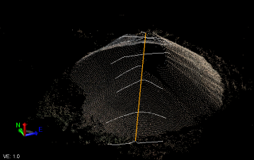
Example using -5.000 left offset and 5.000 right offset:
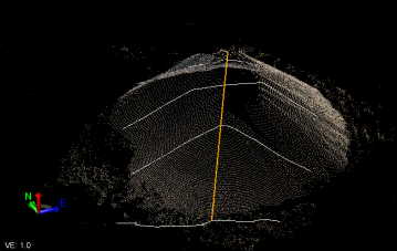
Example using -10.000 left offset and 10.000 right offset:
- Select Settings as follows:
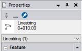
- Layer - Select the layer on which to display the cross-section lines. Or, select <<New Layer>> to create a new layer for the cross-section lines.
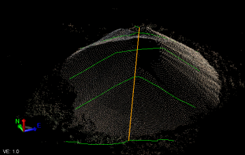
You can use the layer properties to specify the style and color of the resulting cross-section lines. Following is an example where the lines were assigned to a new layer with the layer color set to green.
- Point cloud region - Optionally, select a single point cloud region to which the cross-section extraction will apply. Otherwise, select <None> to specify the extraction be applied to all visible regions.
- Search width - Specify the width from the selected line out to which the software will search for scan points to be used to extract the cross-section(s).
Hint: Try experimenting. Depending on the density of the point cloud, a smaller search width (for example, 0.010) will reduce processing time and may still provide excellent results.
- Minimum segment length - Check this check box and specify the minimum distance between cross-section vertices. If vertices fall within this distance, they are removed, resulting in smoother lines.
- Include overhang - Check this check box to extract cross-sections from overhanging point clouds.
- Auto-close section lines - Check this check box to create closed linestrings for the extracted cross-sections when scan points cannot be located to complete the cross-section line. (Typically, you would select this option for tunnel point clouds which may not have scan points in the bottom of the tunnel.)
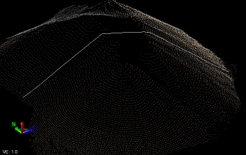
Open cross-section lines:
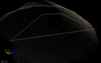
Closed cross-section lines:
- Layer - Select the layer on which to display the cross-section lines. Or, select <<New Layer>> to create a new layer for the cross-section lines.
- Click the Apply button to create the cross-section line segments.
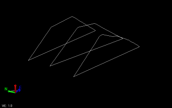
Cross-section linework displayed without a point cloud:
If you do not get satisfactory results, you can press Ctrl + Z to undo and try again.
To delete a cross-section, select its linework, right-click, and select Delete.
Note: If you extracted cross-sections from an alignment, the resulting cross-section linestrings will be named based on the stations where they were created.