Create and Edit an Overexcavation Template
Use the Overexcavation Template Manager command to create one or more complex profile shapes for overexcavation areas (holes and trenches). You can add an unlimited number of instructions to a template to specify the overexcavation surface’s shape. An overexcavation template consists of a bottom, vertical wall, and sloping wall that attaches to a surface (defining the daylight line). The program finds the standard overexcavation bottom/volume, applies the template shape, and then ‘sweeps them together’ to make the wall going around the excavation area.
Once you have defined a template, you can select it for use within the Overexcavation command. The profile is then applied to the sides all the way around the overexcavation hole.
Prerequisites:
- License; See the Subscription Plans page. For a license matrix by command, see the License page in the TBC Community. Also see View and manage licensed features.
To access the command:
- Type OverexcavationTemplateManager (case-sensitive) in the Command Pane > Command box.
This is a hidden command, so it does not appear in the All Commands list or on a ribbon. - In the Overexcavation command's Template list, select <New>.
To create an overexcavation template:
- In the Overexcavation Template Manager dialog, enter a Template name and click New.
You can also copy, rename, and delete overexcavation templates using the other buttons.Tip: Copying a template also copies any instructions it includes, which can give you a good starting point for similar new templates.
- If necessary, modify the Surface tie interpolation value to specify how often (at a distance interval) to generate the overexcavation profile along the closed overexcavation bounadry. Surface tie interpolation represents the distance between template inserted tangent to and along the closed overex boundary. Then connection lines are added between each of the templates. So, for example, if your overex boundary is 100 long and you specify interpolation of 10, you will get 10 templates inserted (at 0 through 90). This is similar to the sampling interval for corridor templates.
Note: In most cases, using the Surface tie interpolation default value of 5 will suffice. Generally, the simpler the overexcavation boundary/closed shape, the longer interpolation distance can be; the more complex shape, the shorter it should be.
- With the new template selected in the list above, select a Type below the Instructions group:
- Distance - Add a sloped or 'vertical' profile segment at the bottom corner using a Width and Height.
- Slope to daylight - Add a profile segment based on a Slope. This instruction is always at the top as it connects to the existing ground. Typically, this will be the last instruction you add.
- Slope with width - Add a profile segment based on a Width and a Slope.
- Slope with height - Add a profile segment based on a Height and a Slope.
By default, any instruction you add will go straight up to the daylight line (green dot), except for the Slope with daylight type, which will go at an angle from the last instruction until it hits the daylight surface. When you add this, the Slope to daylight type is disabled because you can only have one daylight intersection.
Note: How you enter slope as a ratio depends on the Slope ratio type defined in Project Settings > Units > Vertical Angle.
Tip: Add instructions from the hole/trench bottom upwards (the instructions appear in the list in the order you add them, with the final Daylight instruction always on the bottom).
Tip: See the Examples section below for guidance on how to add instructions to achieve common profiles. You do not generally add a segment for the bottom of the hole/trench. - Enter the required values and click the Add button. In the cross-sectional graphic view:
- The gray grid represents the earthen area being cut/overexcavated.
- The red dot represents the edge of the overexcavation wall, which is the point from which the lowest instruction is starting.
- Red lines represent the specified cut barrier alogn each instruction you add.
- The topmost green line is the final slope to daylight. This top segment is an arbitrary length tie to daylight since the program does not know where the surface (which may undulate) is yet.
- The green dot is the daylight line on the existing ground surface.
Note: Instructions in the list are shown top-down (from the top of the hole >down to the bottom) in the cross-sectional view.
Note: Surfaces can never have a perfectly vertical wall because one point cannot be directly above another, and overhangs ('over-vertical' walls) are not possible either.
Note: Value units in the table are based on Project Settings > Units.
- Use the Delete, Replace, Move Up, and Move Down buttons to edit the selected instruction.
To edit an overexcavation template:
- Right-click an existing overexcavation's profile line and select Edit.
Options:
- Delete - Remove a selected instruction.
- Replace - Click this after you edit an existing value in an instruction.
- Move up/down - Move an instruction up or down in the order. You cannot move an instruction above the top/daylight instruction or below the bottom/floor instruction.
Note: You cannot use Undo in the Template Manager; simply delete or replace unneeded/incorrect instructions.
Examples:
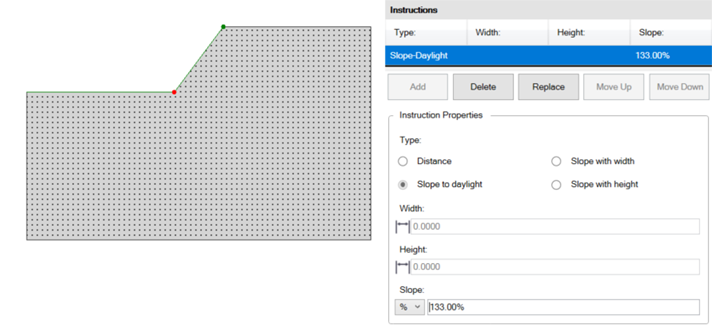
This profile can be built with just a Slope to daylight.
Since you may not know where daylight is, you can just repeat well the steps to a height well above and the profile will stop at the existing ground surface.
