Create CAD Tunnel Cross-Sections
Use the Create CAD Tunnel Cross-Sections command to automatically generate either or both of the following:
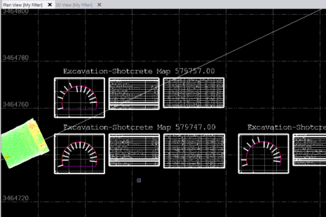
- 2D cross-section diagrams and tables created at specified tunnel intervals and displayed in the Plan View at the location you specify.
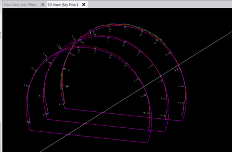
- 3D linework and labels created and inserted at specified tunnel intervals in the 3D View.
The cross-sections help reduce the time required to create CAD-based deliverables from tunnel survey data, such as for construction verification and documentation of excavation, shotcrete, and final lining.
Prerequisites:
See the Subscription Plans page. For a license matrix by command, see the License page in the TBC Community. Also see View and manage licensed features.
To create CAD tunnel cross-section diagrams:
- Select Project Settings in the Quick Access Toolbar and do the following:
- In the left navigation pane in the Project Settings dialog, select View > Tunnel Inspection View > Cross-Section View to view the properties that define the look of any new CAD tunnel cross-section diagrams you create.
- Change any of the Cross-Section View properties s necessary.
For more information, see "Tunnel Inspection View" section of the table in View Settings.
- Select Create CAD Tunnel Cross-Sections in Tunnels > Tools to display the Create CAD Tunnel Cross-Sections command pane.
- In the Inspection map drop-down list, select the inspection map from which you want to create cross-section diagrams.
- In the Output field, select whether you want to create 2D cross-section diagrams and tables (displayed in the Plan View) or 3D linework and labels (displayed in the 3D View).
- In the Start station and End station fields, enter the stations between which cross-sections will be created.
By default, the start and end stations for the tunnel alignment are selected.
- In the Station interval field, enter or select in a graphic view the interval distance at which cross-sections will be created.
- If you are creating 2D cross-section diagrams:
- In the Number of columns field, enter the number of diagrams to display on each line in the display.
- In the Scale the cross-section view image field, enter the scale to apply to diagrams.
- In the Layer drop-down list, select an existing layer on which to display the cross-section diagrams. Or select <New> to create a new layer to use.
- In the Text style drop-down list, select the text style you want to apply to text displayed in the diagrams.
- If you are creating 2D cross-section diagrams, in the Location field, select or enter a coordinate that corresponds to the lower-left corner of the first diagram to be displayed in the Plan View.
- If you are creating 3D linestrings, optionally check the Include delta lines and labels check box to include this information in cross-sections displayed in the 3D View.
- Click Apply or OK
A progress bar displays in the TBC Status Bar showing the progress of the diagram creation process. When it is complete, the new diagrams display in the appropriate graphic view.