Extract Filtered Point Cloud Regions Based on Elevation
Use the Advanced Point Cloud Filtering command to filter a point cloud by extracting a new region based on the detected point elevations within rectangular sampling cells of a specified size applied across the point cloud. This is primarily helpful when trying to create a separate point cloud region for bare ground that does not include low-lying grass and other vegetation, but instead includes only the lowest points in the cloud, at ground level. Optionally, apply the advanced filter to a subset of points in the selected point cloud by specifying a polyline along with horizontal/vertical offsets to shorten processing time and generate more focused, cleaner output. Or, specify that the extraction process automatically apply a dynamic cell size as necessary to account for fast elevation changes in your point cloud
Prerequisites:
- See the Subscription Plans page. For a license matrix by command, see the License page in the TBC Community. Also see View and manage licensed features.
- For best results when using this command to extract a bare-ground point cloud region, you should first classify the ground-level points using the Extract Ground command or Extract Classified Point Cloud Regions command.
To extract filtered point cloud regions:
- Select Advanced Point Cloud Filtering in Point Clouds > Regions to display the Advanced Point Cloud Filtering command pane.
- Click in the Select point cloud regions field and then, in the Project Explorer or a graphic view, select one or more existing point cloud regions from which you want to extract a new filtered-by-elevation region.
- In the Filtered region name field, enter a name for the new region you are going to extract.
- In the Cell size field, enter a single size for the rectangular cells to be used for sampling and filtering, each of which, after running the command, will include only a single point based on the Filtering strategy option you select.
You might want to experiment with different cell sizes to filter the point cloud region as necessary to meet your needs. The smaller the cell size you enter, the denser will be the extracted point cloud region, but it will require increasing memory consumption and lengthening processing time as necessary.
- Optionally, to specify that the extraction process automatically apply a dynamic cell size as necessary to account for fast elevation changes in your point cloud, do the following:
- Check the Dynamic cell size check box.
The size you specified in the Cell size field size is dynamically decreased as necessary to include more points on inclines, helping to ensure data precision.
- Enter the Minimum significant elevation difference distance.
Cells containing points with an elevation difference equal to or greater than this distance will be split into smaller cells, resulting in more points and more detail.
- Enter the Minimum dynamic cell size.
Cells of this size will no longer be dynamically split into smaller cells.
Note: To accommodate dynamic cell sizing, the Minimum dynamic cell size should be two or more times smaller than the size specified in the Cell size field. However, if the cell size is too small, it can result in an unnecessary level of detail, increased memory consumption, and lengthy processing time.
- Check the Dynamic cell size check box.
- Select the appropriate Outlier Point Filter option.
This can help eliminate "noise" points to varying degrees based on the option you select.
One of the filtering options is required if you checked the Dynamic cell size check box.
- In the Filtering strategy drop-down list, select the option to use to determine the point elevation for the single point within each sampling cell.
Minimum elevation is the default and is used for bare ground.
- In the XY position of filtered points drop-down list, select the option for horizontal placement of the point within the sampling cell.
- Actual location - The point's horizontal location is not changed.
- Center of the cell - The point is moved to the horizontal center of the sampling cell.
Note: The Center of the cell option may not be suitable when working with sloping terrain because once the point is moved horizontally, it may no longer be located on the surface.
- Optionally, if you want to apply the filter just along a polyline, do the following:
- Check the Apply filter by polyline check box.
- Click in the Select polyline field and then select the polyline you want to use for filtering.
- In the Horizontal offset field, enter (or measure in a graphic view) the horizontal distance on either side of the selected polyline to which you want to apply the filter.
- Optionally, in the Vertical offset field, enter (or measure in a graphic view) the vertical distance above and below the polyline to which you want to apply the filter.
If no Vertical offset distance is entered, the filter will be applied to all points above and below the the polyline within the Horizontal offset distance.
- Optionally, select to exclude cells with sparse point cloud density from the extraction as follows:
- In the Advanced Point Cloud Filtering command pane tool bar, click the Advanced Setting icon to display the Advanced Point Cloud Filter dialog.
- Check the Exclude cells with sparse point cloud density check box.
- Enter the Minimum number of points required in a cell.
If the cell does not include the minimum number of points specified, it is ignored during the filtering process. This might be useful for areas near the edge of the point cloud or areas obscured by other objects. Since they typically have a sparse number of points, their related sampling cells would be ignored.
- When you are ready, click the Filter button
When the process is complete, the newly extracted region is displayed as a new node nested beneath the parent Point Cloud Regions node in the Project Explorer. You can use the View Filter Manger to hide the new region, view it exclusively, or view it along with other selected point cloud regions.
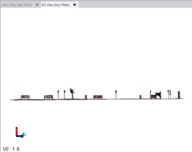
Following is an example of a side view of an unfiltered point cloud region.
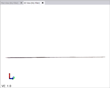
This next example shows the extracted point cloud region when the Minimum elevation option was selected for filtering. In this case, the extracted region can be considered to be "bare ground" because all of the scan points other than the minimum-elevation point in each sampling cell were excluded.
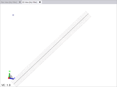
This final example shows the resulting point cloud region when the Minimum elevation option was selected for filtering, along with a polyline and specified offsets (one point per sampling cell):