Create Points and Lines from BIM Objects
Use the Create from BIM command to create points from BIM/IFC objects using either or both of the following methods:
- Create points from mesh centroids using either individual mesh centroids, the BIM object's geometry centroid, or the BIM object's center-of-gravity property.
- Create points from mesh faces using either all selected mesh faces, all horizontal mesh faces only, the lowest horizontal mesh faces, or pipe/beam end faces.
Prerequisites:
- See the Subscription Plans page. For a license matrix by command, see the License page in the TBC Community. Also see View and manage licensed features.
- BIM objects
To create points from BIM objects:
- Select Create from BIM in CAD > Points to display the Create Points from BIM command.
- Click in the Select BIM objects field and then, in a graphic view, select the BIM object(s) for which you want to create points.
Click the Options button for more selection options.
Note: Optionally, when working with 3D mesh objects, you can click the Internal Select Mode icon located in the TBC Status Bar (or press Ctrl+F) to toggle on and off the Internal Select mode. This mode enables you to select just one or more faces of a mesh object with which you want to work, as opposed to all of the object's faces being selected when you select the object. This gives you more precise control over where points will be created on the BIM object. Press the Ctrl key to make multiple face selections on one or more mesh objects.
- Select either or both of the following methods for creating points from the selected BIM object(s):
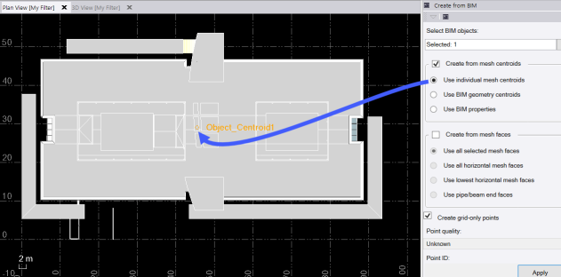
- Create from mesh centroids - Select this method to create a point at the center-of mass of the object mesh using one of three options:
- Use individual mesh centroids - This option creates a point at the centroid of each individual mesh in a BIM object. Note that some objects, like ones labeled as “assemblies", can be made up of dozens of meshes to represent nuts and bolts. If an IFC mesh is selected, this option will behave exactly the same as if you had selected Use BIM geometry centroids for that mesh.
- Use BIM geometry centroids - This option totals the location of every geometry element in a BIM object and creates a point at the center of that range. BIM objects without geometry will not create a point. If an IFC mesh is selected, this option will behave exactly the same as if you had selected Use individual mesh centroids for the selected mesh.
- Use BIM properties - This option creates a point based the calculated center-of-gravity values for the mesh, which are standard in IFC creation.
In the following example, a point was created based on the mesh centroid for the entire IFC building object, as shown in the Plan View.
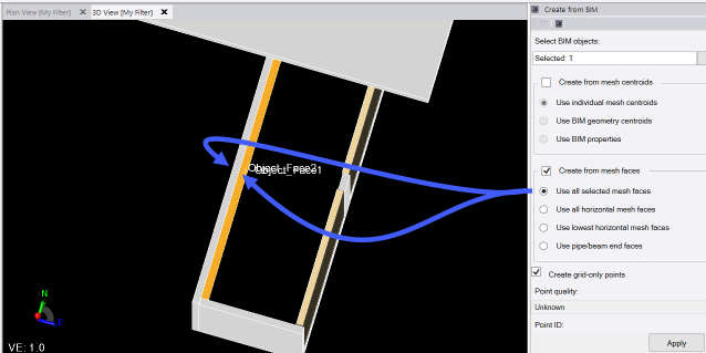
- Create from mesh faces - Select this method to create a point at the center of mesh faces using one of four options:
- Use all selected mesh faces - This option will create points only at the center of selected faces on a mesh. If a whole mesh is selected (for example, you are not using Internal Select Mode), a point will be created for each face of the mesh.
- Use all horizontal mesh faces - This option will create points at the center of selected faces on a mesh only if they are completely horizontally flat. Note that this is a quick solution for creating points at the tops and bottoms of columns for instance. If you select a non-horizontal face, then run the command with this option selected, no points will be created.
- Use lowest horizontal mesh faces - This option will create points at the center of any horizontal faces at the lowest elevation of the selected mesh. If the Internal Select Mode is used to select only some mesh faces, this option will create points only on faces that are also selected.
- Use pipe/beam end faces - This option will cause the command to attempt to find a pair of end faces on which to create points based on a mesh's overall composition. Note that there is always a chance, given the possible complexity of mesh geometry, that incorrect faces will be selected, or that no pair will be found, even if it looks like there should be.
In this example, a point was created at the center of each of the two mesh faces of the selected object, as shown in the 3D View.
- Create from mesh centroids - Select this method to create a point at the center-of mass of the object mesh using one of three options:
- Optionally, check the Create grid-only points check box if you want to create points with X, Y, and Z grid coordinates only. Leave it unchecked if ou want to create points using global or local latitude and longitude coordinates.
- In the Point Quality drop-own list, select the appropriate quality for the newly create points.
- Optionally, do any of the following:
- Change the default Point ID naming scheme to be used for the new points. Optionally, replace {object} with a custom name to use as a prefix for the point name automatically applied after the underscore (Centroid, Face, or FromBIM for both options) followed by a number. Or enter any point name (or no name at all) to be applied to each point automatically followed by a point number.
- Change the Layer on which the new points will be created.
- Type or select a Feature code to be added to the new points.
- Click Apply to create the points.
- The new points are displayed in graphic views and in the Project Explorer.
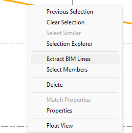
To extract BIM lines
Use the Extract BIM lines command to create linestring copies of each selected BIM object that contains line segments and arcs. This command only joins arcs and line segments if they have the same UCS. Linestrings are created on the same layer as the layer assigned to the BIM Entity it was extracted from.
- Click Extract BIM lines, or enter ExtractBIMLines in the Command pane.
- Click in the Selection field and then, in a graphic view, select the BIM object(s) for which you want to extract lines and arcs.
Click the Options button for more selection options.
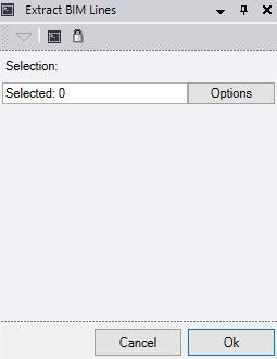
- Click OK to extract the lines.
