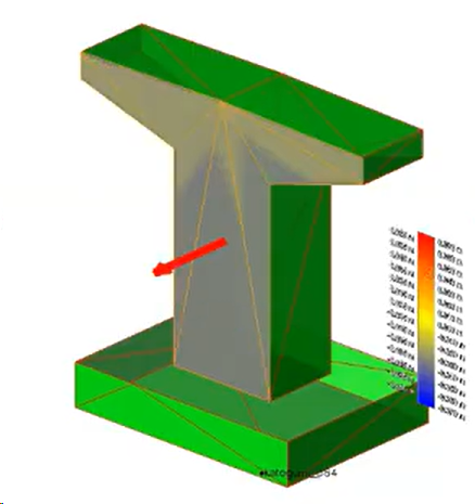
Explode BIM to Projected Surfaces and Create a Point Cloud Heatmap
Use Explode BIM to projected surfaces to take an imported IFC model and explode it onto projected surfaces. Use the Create Point Cloud Heatmap command to QA/QC the completed 3D design surfaces by generating a deviation heatmap between a design surface and a measured point cloud. Designed for structures like highway bridge support columns, the tool creates projected surfaces for vertical structures, incorporates surface direction inversion options, and uses color regions.
Prerequisites:
- See the Subscription Plans page. For a license matrix by command, see the License page in the TBC Community. Also see View and manage licensed features.
- A point cloud / point cloud region co-located with the design
- The heatmap design surface must be a Projected Surface from Explode (not a TIN/surface from points)
To explode an IFC Surface and create a point cloud heatmap:
- Use the Import command to import an Industry Foundation Class (.ifc) model.
- SelectExplode BIM to Projected Surfaces in BIM > Tools to open the Explode BIM to Projected Surfaces pane.
- In the graphic view, select an IFC model and click Apply.
Project Explorer or View Filter Manager shows the new projected surfaces.
- Select Create Point Cloud Heatmap in BIM > Tools. The Create Point Cloud Heatmap pane opens.
- Enter a Name for the heatmap.
- Select the Point cloud region in the 3D view.
- Select the Projected surface in the 3D view.
Note: You can only select Projected Surfaces.
- Optionally, click Invert surface direction to change the direction of the Projected Surface. An arrow indicates which way the colors are measured.
The heatmap uses the IFC surface direction to determine the color of positive and negative surface deviations.
- Optionally, click Create color legend to create a legend displaying the colors of the heatmap on the heatmap.
This creates a separate Legend object called [name] Legend, which is appended to the heatmap.
- Optionally, expand the Advanced Settings section.
- Click in the Grid reference point field and enter a grid reference, or click in the graphic view to select a point. The default is the top-left.
- Enter the Grid size. The default is 0.10 m; the minimum is .001 m.
- Enter the Heatmap range. The default is ±0.07 m.
- Enter a Maximum deviation. The default is ±0.10 m.
- Enter the Edge exclusion range. the default is 0.050.
- Enter the Color pitch. The default is 0.005 m the minimum is 0.001 m.
- Enter a Grid line size. The default is 0.01 m. This number must be smaller than the Grid size.
- Use the dropdown menus to select a color for positive and negative surface deviations, the Intermediate color to show gradiations, and the Grid color.
- Click Apply to create the heatmap or Cancel to close the Point Cloud Heatmap pane.
- Heatmaps are generated as GeoreferencedImage3D, so you can export a heatmap using any exporter that supports GeoreferencedImage3D. See Export Data.