Specify Local Site Settings
Enter local site settings to create a ground coordinate system to accommodate elevation differences between your site and the ellipsoid. The scale factor can be calculated for you. Use the options to project grid coordinates onto locally surveyed ground coordinates so that grid distance matches ground distance.
You should define local site settings for the project location at the start of the project because this information is used in calculations. The application uses:
- The project latitude to calculate the earth's radius
- The project latitude and longitude to define the grid scale factor
- The project height as the default elevation and to calculate the elevation factor
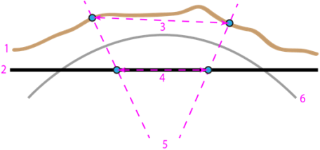
- Surveyed ground (in profile)
- Projected grid
- Ground distance (between surveyed points)
- Grid distance (between grid points correlated with the surveyed points)
- Projection (normal to the ellipsoid)
- Ellipsoid
Making this conversion (matching grid to ground) makes it easier to:
- Georeference images
- Edgematch PDF site plans
- Show grid coordinates that reflect the measured ground distance
To specify local site settings:
- Select Local Site Settings in Survey > Network. TheLocal Site Settings command pane displays.
- Select a coordinate system to display in the Coordinate type list. Any changes take effect immediately.
If you select Grid:
- Click in the Northing box.
- Pick a point in a graphic view, right-click for options, or type coordinates in the Northing and Easting boxes to specify the location for the local site.
- Pick a point in a graphic view, right-click for options, or type a value in theElevation box.
If you select Local or Global:
a. Click in the Latitude box.
b. Pick a point in a graphic view, right-click for options, or type coordinates in the Latitude and Longitude boxes to specify the location for the local site.
c. Pick a point in a graphic view, right-click for options, or type a value in theHeight box.
- To use a ground scale factor, check the Use ground coordinates box.
- From the drop-down list, select one of these options:
Scale ground coordinates from project location to compute ground coordinates using the following formula:
Ground Easting= (Grid Easting - False Easting) * Combined Scale Factor + False Easting
Ground Northing = (Grid Northing - False Northing) * Combined Scale Factor + False NorthingScale ground coordinates from grid (0.0) to compute ground coordinates using the following formula:
Ground Easting = Grid Easting * Combined Scale Factor
Ground Northing = Grid Northing * Combined Scale FactorNote that if if you scale ground coordinates from 0.0, you cannot export the following legacy file versions:
- JXL prior to v6.33
- JOB prior to v25.10
- DC prior to 11.10
Note: JXL files created using the new scaling 0.0 feature are not compatible with Trimble Access and Trimble Business Center prior to 2025.20. They can be imported in TBC prior to 2025.20, but they will produce the wrong coordinates.
- From the drop-down list, select one of these options:
- Type a value in the Ground scale factor box, or check Compute ground scale factor from project location to have the value computed.
- To close the dialog, click.
To view the local site settings:
- Select Project Settings in the Quick Access Toolbar. The Project Setting dialog displays.
- SelectCoordinate System and then Local Site. The read-only Local Site settings display.
