Understanding Site Calibration
The site calibration process establishes the relationship between global coordinate data collected by GNSS receivers and local control positions (expressed as a local map grid with elevations above sea level). This relationship is defined by a series of mathematical transformations. Site calibration enables you to pair up GNSS and local control points to be used in the calibration. (GNSS coordinates must be derived from GNSS points and observations, and grid points must be derived from grid points and terrestrial observations). This software then computes and applies the mathematical transformations using least squares.
The mathematical transformations that are applied in order to convert global coordinate positions to grid coordinates are:
- A datum transformation to convert the global latitude, longitude, and ellipsoidal height coordinates to latitude, longitude, and ellipsoidal height coordinates relative to the ellipsoid of the local map grid.
- A map projection to convert the local ellipsoid latitude and longitude coordinates into local map grid northing and easting coordinates (the height value is not altered in this process).
- A geoid model to global coordinate height to get approximate elevation above sea level.
- A horizontal adjustment of the transformed grid coordinates to best fit local control data. This adjustment allows for any local variations in the projection system that cannot be accommodated in the overall datum transformation.
- A height adjustment to convert the heights above the local ellipsoid or elevations derived from the geoid to local control elevations above sea level.
The horizontal and vertical adjustment are stored as part of the coordinate system definition for the project. All GNSS points in the database are updated using the calibration parameters, resulting in more accurate local grid coordinate values.
You can save the new coordinate system definition (which includes the calibration parameters) as a site for use in future projects in the same area.
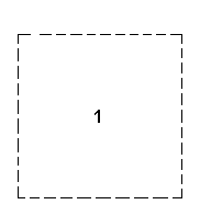
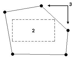
If you save a calibration as a site with the intention of using the site in another project, make sure that the project area is fully enclosed by the points used in the calibration. For example, in the following diagram, it is valid to use the site definition for project B, but not for project C.
|
|
|
|
1. Project C area |
2. Project B area 3. Points used in calibrating Project A |
If you use the key in Trimble® Survey ControllerTM to start a Real Time Kinematic (RTK) base, and transfer the Survey Controller (.dc) file to this software, the base position, and therefore all rover points from the base, are of unknown quality (for all components, horizontal, height, and elevation).
Note: After performing a site calibration, if you apply local site settings, the calibration you have defined will become invalid and be removed. An error message warns you that continuing will remove the site calibration.
Using geoid models
If the coordinate system for the project defines the use of a geoid model for point elevation determination, then elevations are determined directly off the WGS-84 heights by interpolation on the geoid model grid. However, it is still possible to apply a height adjustment on top of the elevations produced by a geoid model to allow for small local variations that a large scale geoid model cannot take into account. Elevations determined from a vertical calibration are given a survey quality.
Rules for ensuring a useful calibration:
- WGS-84 coordinates must be relatively correct.
It is possible to generate autonomous GNSS points. However, you should not use more than one autonomous WGS-84 point in a calibration, for example make sure that only a single base station has been set up using the Here key in Trimble Survey Controller. Other base stations should be set up on positions measured by a GNSS vector in terms of the autonomous base station. This defines the relationship between them and allows you to perform a calibration with points used from either base station correctly. This is described below:
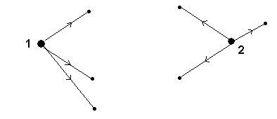
The following figure shows no relationship between the base stations:
|
|
|
Points from Base 1 and Base 2 should not be used for calibration. |
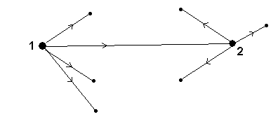
In the following figure, a relationship is defined between the base stations by occupying the second base station using the first base station:
|
|
|
Points from Base 1 and Base 2 can be used for a calibration. |
- The best possible WGS-84 coordinates should be used for the initial base station in a survey.
The precision of GNSS vectors (real-time or post-processed) is affected by the accuracy of the base coordinate. An error of up to one part per million (1 ppm) can be introduced for each ten meters of error in the base coordinates. For example, if your primary WGS-84 reference point has an error of one hundred meters and your baseline is two kilometers long, you may have an unnecessary extra error of two centimeters in your GNSS vectors.
