Add a Coordinate to a Point
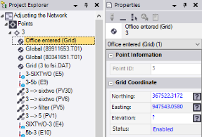
You can add a coordinate to a point when, for example, you need to include a position for control or stakeout that was not observed in the field or otherwise recorded and imported in a points file. When you add a coordinate to a point, a coordinate object named Office entered is created and is represented by a node that displays nested beneath the point node in the Project Explorer.
Note: Add a coordinate to a point only when you are sure that you want to use this coordinate instead of an observed coordinate. During the computation of the project, added coordinates are used in preference to observations of the same quality. This ensures that a designed point is used in preference to a staked point.
Prerequisites:
- point
To add a coordinate to a point:
- Do one of the following:
- Pick the point in a graphic view or select it in the Project Explorer, right-click, and select Add Coordinate from the context menu.
- If the point's Properties pane is open, click the Add Coordinate icon located on the pane's toolbar.
The Add Coordinate command pane displays.
- In the Coordinate type list, select the type of coordinate you want to add.
Your selection determines which coordinate fields are displayed.
Note: You can add only one grid, local, and global coordinate to a single point. If each coordinate type has already been added to the point, the Add Coordinate icon is unavailable.
- Click in the appropriate horizontal coordinate field and either type in a coordinate value or make a selection in a graphic view. Then do the same in the Height/Elevation field.
Note the following when making your selection:
- Optionally, right-click in any coordinate field for coordinate geometry (COGO) selection options.
- Optionally, click the Auto advance On/Off button located to the immediate right of the Height/Elevation field to specify whether or not you want to be prompted to enter this value when adding a coordinate.
- Elevation is measured from sea level. Height is measured from the ellipsoid.
- Click the Planar quality button located to the right of each coordinate field to specify the planar quality for the coordinate.
 Control - National Geodetic Survey (NGS) surveyed coordinate of the highest quality.
 Survey - Surveyed coordinate of the second highest quality.
 Mapping - Coordinate of low to average quality.
 Unknown - Coordinate of the lowest or unverified quality.
- Select the appropriate coordinate status in the Status drop-down list.
This determines whether and how the coordinate is used during the project computation process.
- Enabled - Include the coordinate when the project is computed.
- Disabled - Exclude the coordinate when the project is computed.
- Enabled as Check - Used only for error checking except when there is no other way to compute the position for the point.
- Click the OK button or press the Enter key to add the coordinate to the point.
These commands are also available by right-clicking in the graphic view.
The coordinate is added to the point and is represented by a new Office entered node nested beneath the point node in the Project Explorer.
- If the Compute Project
 icon displays on the status bar, click it to recompute and update the coordinates in the project.
 - To see how the added coordinate affected the point's position, right-click the point's node in the Project Explorer and select Point Derivation Report.
Note: You can edit the coordinates for imported CAD points in the Properties pane, but CAD points are not used in computations.
