Create and Edit Points
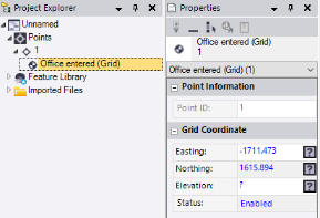
You can create a point in your project when, for example, you need to include a point for control or stakeout that was not observed in the field or otherwise recorded and imported in a points file. When you create a point (see "Create a Point" below), in addition to the new point object, a coordinate object named Office entered is created and is represented by a node that displays nested beneath the point node in the Project Explorer. You can, if necessary, edit the the office-entered coordinate in the coordinate's Properties pane to change the position of the point (see "To edit a point" below).
Prerequisites:
- If you plan to assign feature codes and attributes to the point, you must first import a Feature Defintion Library (.fxl) file into your project.
To access the command:
Do one of the following:
- Select Create Point in CAD > Points.
- Right-click Points in the Project Explorer, and select Create Point from the context menu.
To create a point:
- In the Create Point command pane, optionally change the default ID displayed in the Point ID field.
Point IDs are not case-sensitive. You can change any default point ID before you create the point. Note the following regarding default point ID sequencing:
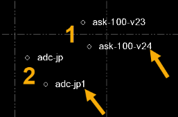
- If the Point ID includes a number, it will, by default, automatically increment to the next unused number when you create a subsequent point. If the Point ID includes multiple numbers separated by, for example, hyphens or dashes, the right-most number is incremented. (See 1 below).
- If the Point ID includes only alpha characters, it will, by default, automatically append an incremented number to the alpha string when you create a subsequent point. If the Point ID includes multiple alpha strings separated by, for example, hyphens or dashes, the right-most alpha string is incremented. (See 2 below).
- Select the layer on which you want the point to reside in the Layer list, or select <<New Layer>> to create a new layer for the point. Optionally, type any part of the layer name in the field. The function is case insensitive.
- In the Feature Code field, optionally enter a feature code for the point. (As an alternative, see step 4.)
Feature codes are not case-sensitive.
As an alternative to typing in a feature code, you can select the Browse button located to the right of the Feature code field and select a feature code from the list displayed in the Feature Code Editor dialog. You can also use this dialog to enter attribute values as necessary.
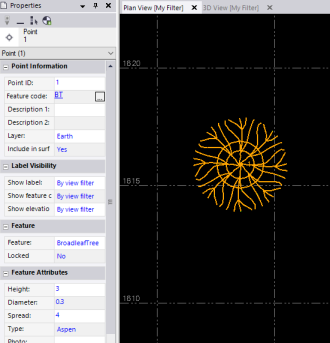
Once you enter a feature code, the associated attributes and their default values are also displayed in the Attributes section of the Create Point command pane. You can change any of the attribute values as necessary, and you can add a media file if applicable.
Note: You must import a Feature Defintion Library (.fxl) file into your project before using the Feature Code Editor dialog.
- Optionally, check the Measure codes mode check box to display the Measure codes controls.
This mode allows you to quickly and easily assign feature and control codes to the point using a customized grid as is used in Trimble Access 2020. For instructions, see Measure Feature Codes when Creating a Point.
- In the Coordinate type list, select the type of coordinate you want to use to define the point's position.
Your selection determines which coordinate fields are displayed.
- Click in the appropriate horizontal coordinate field and either type in a coordinate value or make a selection in a graphic view. Then do the same in the Elevation and/or Height fields.
Note the following when making your selection:
- Optionally, right-click in any coordinate field for coordinate geometry (COGO) selection options.
- If you are making a horizontal coordinate selection in a point cloud (either in 3D View or Station View), optionally click the Point Cloud Smart Picking button located to the right of each of the horizontal coordinate fields field to display the Point Cloud Smart Picking window, which allows you to easily create a point on a curb, gutter, or roadmark.
- Optionally, click the Auto advance On/Off button located to the immediate right of the Height and Elevation fields to specify whether or not you want to be prompted to enter either or both of these values when creating a point. For example, if you select Off for both of these fields, you are not prompted to select/enter a value in either field and a new point is created as soon as you select/enter horizontal coordinates.
- Elevation is measured from sea level. Height is measured from the ellipsoid.
- Click the Planar quality button located to the right of each coordinate field to specify the planar quality for the coordinate.
 Control - National Geodetic Survey (NGS) surveyed coordinate of the highest quality.
 Survey - Surveyed coordinate of the second highest quality.
 Mapping - Coordinate of low to average quality.
 Unknown - Coordinate of the lowest or unverified quality.
- Select the appropriate point coordinate status in the Status drop-down list.
This determines whether and how the point's coordinate is used during the project computation process.
- Enabled - Include the coordinate when the project is computed.
- Disabled - Exclude the coordinate when the project is computed.
- Enabled as Check - Used only for error checking except when there is no other way to compute the position for the point.
- If you assigned a feature code with attributes to the point, change any of the values in the Attributes section as necessary. Or, if applicable, add or remove reference to a media file.
- Click the Add button or press the Enter key to create the point.
These commands are also available by right-clicking in the graphic view.
The point and an office-entered coordinate are represented by new nodes in the Project Explorer.
If a feature code was entered for the point, the code is automatically processed and the associated feature and its attributes and symbols are added as properties to the point. Symbols display in the graphic views. (There is no need to process the feature code using the Process Feature Codes command.)
To edit a point:
To change the position of a survey point, you must add or edit a coordinate object associated with it. Office-entered points, however, can be edited directly in the point's Properties pane.
- To edit the position of a point that has a coordinate node in the Project Explorer, right-click the node that you want to edit and select Properties from the context menu. In the Properties pane, edit the coordinate values as necessary.
Note: Only office-entered coordinates can be edited. If you try to edit an imported coordinate, an office-entered coordinate with the new location is added to the point.
- To edit a point that has no coordinate objects, see Add a Coordinate to a Point.
- To edit an office entered point, select it in the Project Explorer or a graphic view, right-click, and select Properties in the context menu. In the Properties pane, edit the coordinate values as necessary.
