Measure Feature Codes when Creating a Point
When creating a point in TBC, you have the option to assign a feature definition code and, optionally, a control code to the point using the Measure codes option in the Create Points command pane. This option allows you to select the feature definition/control group that includes the codes you want to work with, which are displayed on buttons in a customizable grid layout. You can then use your mouse, arrow keys, or keypad (3x3 grid only) to select the code from the grid to assign to the point. Or, you can specify the direction on the grid that you want subsequent code selections to be made for you automatically when you use the same feature definition/control code group to create multiple points, saving you the time it takes to select a code each time you create a point. In addition, you have the option to easily append the assigned code with a numeric suffix that identifies the instance of the code usage.
This workflow matches the workflow used in Trimble Access 2020 and provides a quick and easy way to iteratively add codes to new points.
Note: For instructions on creating a feature definition/control group in TBC, see Work with Feature Definition/Control Groups.
Prerequisites:
- You must first import a Feature Defintion Library (.fxl) file into your project.
To select measure codes layout options:
Before measuring codes when creating a point, you can configure and/or verify the layout and behavior of the code buttons that display in the Measure Codes section in the Create Points command pane for each feature definition/control group you want to use to assign codes.
Note: If you have imported measure codes contained in an MCD (.mcd) file imported along with a corresponding FXL (.fxl) feature definition file, measure code settings may have already been configured and you may not need to make any changes using the Measure Codes Editor dialog as described here.
- In the Create Point dialog, check the Measure codes mode check box.
- Click the Edit button located beneath the code button grid.
- In the Measure Codes Editor dialog, do either of the following:
- Click the New Group button to display the Create Feature Library Group dialog, enter a name for the new group, and click OK. The new group displays in the Feature/control code group drop-down list. The code buttons are empty; you will assign codes later in this procedure.
- In the Feature/control code group drop-down list, select the existing feature definition/control group containing the codes you want to include in the button layout.
- In the Code button layout drop-down list, select the button layout you want to use.
Options are 3x3 through 5x5.
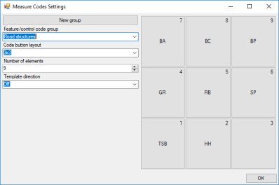
Note: The 3x3 layout includes a number in the top-right corner of each button. These numbers correspond to keypad numbers you can use to assign codes when using a computer keypad with the Create Point command. These numbers display only in the 3x3 format. For more information on this feature, see "To measure feature codes when creating a point" later in this topic.
- In the Number of elements field, specify the number of buttons to display in the selected code button layout.
For example, you may want to use a 3x3 layout but display only 8 buttons instead of 9.
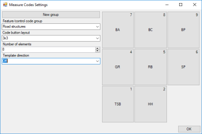
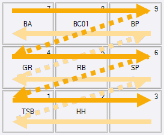
- In the Template direction drop-down list, specify the direction you want subsequent code selections to be made when you use the same feature definition/control code group to create multiple points.
For example, you might be creating four points every 10m along a road corridor to identify the edge of pavement, gutter, top of curb, and back of curb. Depending on the direction you select, each of these codes could be automatically selected in sequence as you create each of the four points, saving you the time it takes to select each code.
- Off: The highlight remains on the selected button after each point is created.
- Left to right: In this 3x3-layout example, the highlight moves from 7–9, then 4–6, then 1–3.
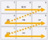
- Right to left: The highlight moves from 3–1, then 6–4, then 9–7.
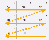
- Zig zag: The highlight moves from 7–9, 4–6, 1–3, and then from 3–1, 6–4, 9–7, and then 7–9, and so on
- If you are configuring buttons for a new group, click any empty button and use the Feature Code Editor to add a code to it.
Regardless of the button you select, the codes will be added in sequence to the button grid starting at the top left and populating buttons left to right, top to bottom. When you are done, you can rearrange them as described in the next step.
- To rearrange the buttons displayed in the grid, drag and drop them to new locations as necessary.
Note that buttons must be displayed contiguously from left to right and top to bottom. If you drag a button to a location that results in a gap between it and the preceding button, the selected button will move automatically as necessary to fill the gap.
- Repeat as necessary to configure/verify the layout for additional feature definition/control code groups.
- Click OK to save your changes and close the Measure Code Settings dialog.
To measure feature codes when creating a point:
- In the Create Point dialog, check the Measure codes mode check box.
- In the Feature/control code group drop-down list, select the group containing the codes you want to assign to the new point.
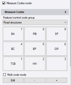
- If you want the ability to add multiple codes to the point, check the Multi-code mode check box.
This allows you to use your mouse or arrow keys to make multiple code button selections, resulting in multiple codes being applied to the point.
- Do one of the following to select a code to assign to the new point:
- Use your mouse to select the code button in the grid.
- Press any of your arrow keys to select the code button in the grid, then press the Enter key.
- If a 3x3 code button layout is displayed, use your computer numeric keypad to select the number corresponding to the code you want to assign.
Notes:
- Numbered keys along the top of your keyboard will not assign a code; you must use the numeric keypad on your keyboard, if you have one. Ensure your keypad is operable by pressing the Num Lock key.
- Keypad entry works only with the 3x3 layout.
- You cannot use the numeric keypad to make multiple selections as described in the previous step.
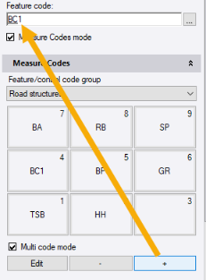
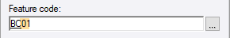
The selected code is displayed in the Feature code field.
You now have the option to append the assigned code with a numeric suffix that identifies the instance of the code usage. For example, BC1 might define the back of curb for one lane while BC2 defines the back of curb for a separate lane. When you add a numeric suffix to a code, it is affixed to the code in the selected code group until you change it.
Note: The numeric suffix does not affect feature code processing. In addition, if you export the project's feature library to an FXL (.fxl) file and reopen the file in a different project or application, the assigned suffices will not be included with the group code.
- Optionally, click the - or + button to increment or decrement the numeric suffix for the selected code.
 To select the format to use for feature code suffixes...
 If the assigned feature code requires a line or block control code (for example, StartLine or EndLine), you can now add it.
- To add a line or block control code to a feature code you just assigned to the new point, or to add another feature code to the point, ensure the Multi-code mode check box is checked. Then, if the code is displayed in the current button layout, click it. If it is not, in the Feature/control code group drop-down list, select a different group containing the code you want to assign and then click the code button.
Note: You can enter additional codes for the point manually, regardless of whether the Multi-code mode check box is checked. Place your cursor in the Feature code field immediately following the assigned code. Press the Space key and enter the control code directly in the Feature code field. Or, press the Feature Code Edit button located to the right of the Feature code field and add the code.
- If your cursor does not automatically move to the Easting field, select to insert it there and continue with the point creation process.
If you selected an option other than Off in the Template direction field in the Measure Codes Editor dialog (see "To select measure codes layout options" earlier in this topic), for each subsequent point you create using the same code group, the next code in the selected sequence will be automatically selected.
To import an MCD file:
Import Measure Codes layout options from a Measure Codes Definition file (.mcd) that was exported from another project or application. For instructions, see Import Measure Codes Definition Files (.mcd).
To export an MCD file:
Export the Measure Codes layout options selected in your project to a Measure Codes Definition file (.mcd) that can be imported into other projects or applications. For instructions, see Export Measure Codes Definition Files (.mcd).
