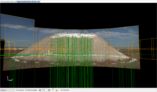
Station View (Referenced Images and Scan Points)
Use the Station View tabs to view one or more referenced images (photographs) and, if applicable, scan points captured with a photo/scan station. You can make photogrammetry measurements or virtual DR measurements (using scan points) directly on the tab.
To view Station View tabs:
Do one of the following:
- In the Project Explorer, select a Station node
 or Image node
 , right-click, and select New Station View.
 Note: If you are going to measure photogrammetry points, you can display one or more Station View tabs as appropriate, along with the Measure Photo Point command pane. Right-click one or more Photo Station, Photo Observation, or Image nodes in the Project Explorer and select Measure Photo Point.
- On any graphic view tab, select the frame for the referenced image you want to view, right-click, and select New Station View. Reference frames are displayed in orange and indicate the location of the images.
Note: To display and be able to select reference frames and images in the graphic views, select the appropriate options in the Advanced View Filter Settings dialog.
- On any graphic view tab, select a photo station, right-click, and select New Station View. Stations are represented by pink camera symbols.
- Select Station View in Views > 3D View. If a referenced image, wireframe, or photo station is selected, the Station View tab is displayed for the selected object. If none of these objects are selected, the Select Image dialog displays, allowing you to select the photo stations and referenced images you want to view on the Station View tab(s). See the following section for more information on using the Select Image dialog.
If you selected a referenced image to view, that image is displayed on the Station View tab along with any other photographic images that were taken from the same station. You view the images from the vantage point of the associated photo station, with the selected image being the primary focus point.
If you selected a photo station, all of the photographic images taken from the photo station are displayed on the Station View tab. Again, you view the images from the vantage point of the selected photo station.
If the photo station was also used to capture scan points, the scan points are also displayed on the Station View tab.
Note: To ensure photo station images display as quickly as possible each time you select to display a station view, the images are re-sampled and initially displayed at a lower resolution until you zoom in, at which time high-resolutions images are displayed.
To select an image using the Select Image dialog:
The Select Image dialog displays when:
- You select to open more Station View tabs than the maximum specified in the Options dialog.
- You select Station View in Views > 3D Viewwhen no referenced image, wireframe, or photo station is selected.
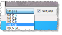
- In the Select Image dialog, select the photo stations or referenced images you want to view in the All stations list.
- Click the Move > button to move the selected items from the All stations list to the Stations to view list.
If the Move > button is disabled, the maximum number of Station View tabs is already open. To open more Station View tabs, you must do one of the following:
- Increase the value displayed in the Maximum number of station views: drop-down list.
- Select less photo stations or referenced images in the All stations list.
- Select one or more photo stations in the Stations to view list, and click the Move < button to remove them from the list.
- When you are done, click OK.
Each photo station included in the Stations to view list is displayed on a separate Station View tab.
Notes:
– Opening too many Station Views at the same time may result in memory usage problems that require automatic photo image down-sampling. For more information, see "Note on computer memory" below.
– You can also change the maximum number of the station views by selecting Options > Photogrammetry.
To move images forward and backward:
To improve viewing, you might want to reorder images so that an image that was behind another image now appears on top of it. For instructions on moving the display of an image forward or backward relative to other images in the view, see Move Images Forward and Backward.
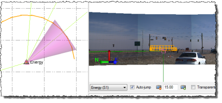
To view an image from a different station:
When the Station View tab is displayed, you can select to view images from a different photo station vantage point by using the Station List located at the bottom of the tab. If the Auto-jump check box is selected, you can simply select the pink photo station in the Station View from which you want to view images.
To remove parallax:
Optionally, check the Remove parallax check box located at the bottom of the Station View tab to ensure observations visually align with their targets in all images.
Note: Parallax is the displacement in the apparent position of an object viewed along two different lines of sight (that is, from different cameras).
To set the default viewing distance:
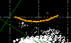
If objects in adjoining images in a panorama do not align correctly in the Station View, you may be able to correct the alignment by selecting a viewing distance that matches the distance from the station to the object of interest. Use any of the following methods:
- Enter the viewing distance in the Viewing distance field located at the bottom of the Station View tab. As an alternative, click the Decrease viewing distance
 button or the Increase viewing distance button
  until the object is most closely aligned in the two images.
 - Select Project Settings in the Quick Access Toolbar. In the Project Settings dialog, select View > Referenced Image and enter a new value in the Viewing distance field.
- Click in the Viewing distance field located at the bottom of the Station View tab. Then select any survey point or scan point (if applicable) to specify that its distance from the station be used for the viewing distance.
To filter images:
When the Station View tab is displayed, you can select which of the images captured with the photo station you want to view on the tab by clicking the View Filter icon located at the bottom of the Station View tab. The icon changes to represent the state of the filter:
-
 - All images displayed
 -
 - Some images displayed
 -
 - All images hidden
In the Image Filter for Station View dialog, check and uncheck check boxes to display and hide panoramas or individual images. Changes based on your selection take place immediately.
In addition, you can check the Show scans for other stations check box to view scans from all stations on the current Station View tab. This is useful if you are using the Virtual DR feature described later in this topic.
To create CAD objects and make measurements on a vertical surface:
You can use CAD tools to create points and linework and make measurements directly on a vertical surface (for example, a building facade) in a station view. You do this by selecting two coordinates to define an infinite vertical depth plane for the surface on which you want to work (using the Define Depth Plane command). After creating a depth plane, you can use the various CAD tools to draw linework or make measurements on the surface represented by the depth plane.For instructions, see Create Linework and Make Measurements on a Vertical Surface in a Station View.
To make measurements and create points and CAD objects using Virtual DR:
If you want to use a Station View with scan points to make distance, angle, or inverse measurements, or create points and lines, check the Virtual DR check box located at the bottom of the tab. This allows you to use the Pixel Picker to select on a referenced photo image the location (pixel) where you want to create a measurement, CAD object, or point. TBC then projects a nearby scan point onto the line-of-sight ray to help calculate the 3D position of the new point. If there are no nearby scan points, an appropriate error message is displayed and you will need to make a new selection.
 More about using the Pixel Picker...
Note: Before using the Virtual DR feature, it is highly recommended that you register the scans in your project. Once the scans are registered, you can select to view all of the scan points in the project on any Station View tab and TBC can then use any of them for the Virtual DR measurement. Just click the View Filter icon located at the bottom of the tab and check the Show scans for other stations check box.
To view the field of vision indicator in the Plan View:
You can display on the Plan View tab a graphical indicator of the field of vision for each station view displayed on an open Station View tab. As you change the field of vision on the Station View tab (for example, zoom in or out, pan left or right, or tilt up or down), the corresponding indicator on the Plan View tab reflects your changes. Select Options in the Quick Access Toolbar and select Photogrammetry to turn the field of vision indicator on and off, and select how the indicator is displayed. See Photogrammetry Options for more information.
Note: If you are experiencing slow performance when viewing a large number of images, you might try selecting Options > Images and selecting the Down-sampled resolution option. This will result in lower resolution images, but should increase performance.
