Measure Angles
Measure the angle between three named points (points with IDs) and/or selected locations.
Prerequisites:
None.
To measure an angle:
- Select Measure Angle in Home > Data to display the Measure Angle command pane.
- Select the appropriate angle measurement type in the Options drop-down list.
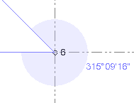
Full Circle example:
Half Circle example:
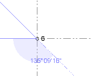
Obtuse example:
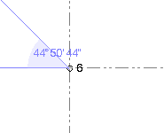
Acute example:
- If you are measuring angles using a Station View with scan points, check the Virtual DR check box located at the bottom of the tab.
This allows you to use the Pixel Picker to select on a referenced photo image the location (pixel) where you want to create a measurement point. TBC then projects a nearby scan point onto the line-of-sight ray to help calculate the 3D position of the new point. If there are no nearby scan points, an appropriate error message is displayed and you will need to make a new selection.
 More about using the Pixel Picker...
Note: Before using the Virtual DR feature, it is highly recommended that you register the scans in your project. Once the scans are registered, you can select to view all of the scan points in the project on any Station View tab and TBC can then use any of them for the Virtual DR measurement. Just click the View Filter icon located at the bottom of the tab and check the Show scans for other stations check box.
- Click in the Start point field, and then either click the "start" point in a graphic view or type a point ID (name) or coordinate (Plan View only; use the format X,Y) in the field.
You can pick either a named survey or CAD point, or an unnamed scan point. If the Free option is checked in the Snap Mode dialog and you are making your selection on the Plan View tab, you can also pick a location where there is no point (not applicable on a 3D View or Station View tab). In this case, only 2D inverse values are calculated.
Optionally, click the Show Snap Options icon located on the command pane toolbar to help make your selection.
You can also right-click in the view to access COGO controls and snaps when picking points.
- In the Pivot point field, select or type the pivot point or location.
- In the End point field, select or type the end point or location.
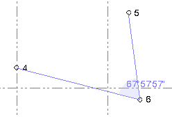
The measured angle is displayed in the Result section.
You can continue to select different points or locations to make additional measurements. (If necessary, you can change to a different graphic view between measurements.)
As you make each measurement, the measurement results are displayed in the Results section and in the History section of the command pane, where all measurements are displayed until you close the project. You can clear the history at any time by clicking the Clear History icon located on the command pane toolbar.
- To save the current measurement displayed in the Results section, do the following:
- Click the Save button.
- In the Save Measurement dialog, optionally rename the measurement and/or change other properties, and select whether or not the angle is horizontal.
- Click the Save button in the Save Angle Measurement dialog.
The stored measurement continues to display in the graphic views, even if you make additional measurements or close the Measure Angle command pane altogether.
Note: To specify whether stored measurements are displayed and/or are selectable in graphic views, select View Filter Manager > Advanced View Filter Settings.
Each stored measurement is represented in the Project Explorer by a new Angle node nested beneath the Store Measurements parent node. You can right-click any stored measurement node and select Properties to view it in the Properties pane, where you can change the name, layer, color, and/or angle measurement type. You can also change whether or not the measurement is horizontal.
To delete a stored measurement, right-click it in the Project Explorer and select Delete.
- When you are done, click in the Angle command pane.
