Register, Refine, and Georeference Point Cloud Scans
Use the Scan Registration (Register) command to register overlapping scans imported from multiple scan stations to ensure they are correctly aligned with each other and, if a survey station setup is included, to survey control, resulting in a single, rigid point cloud.
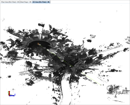
Example of overlapping scan data before registration:
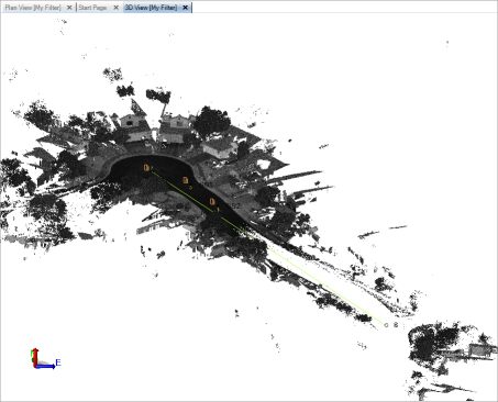
Example of overlapping scan data after registration:
The Scan Registration command supports two major registration workflows:
- Plane-based registration - If your raw scan data was imported from a Trimble TZF (.tzf) or Faro FLS (.fls) file, which does not include scan station position data, use this workflow to easily perform an automatic plane-based registration of the scan stations and their associated scans to each other, typically resulting in a single scan station group and a rigid point cloud. See "To perform a plane-based registration (Trimble TZF and Faro FLS files only)" below for instructions. After performing the registration, you can, if applicable, georeference the point cloud as explained in "To georeference movable station groups" below.
- Pairwise registration - If your raw scan data was imported in a format other than Trimble TZF (.tzf) or Faro FLS (.fls), or if it includes both unmovable scan stations (for example, scanning-capable total stations set up on known positions) and movable scan stations (for example free-standing scanners set up on unknown positions), use this workflow to perform a pairwise registration of the scan stations and their associated scans. This causes the movable scan stations to move into alignment with the unmovable scan stations, resulting in a single station group, which can be further refined if necessary, and a rigid point cloud. See "To perform a pairwise registration" below for instructions.
Note:  Read about station level/tilt compensation...
Prerequisites:
- See the Subscription Plans page. For a license matrix by command, see the License page in the TBC Community. Also see View and manage licensed features.
- It is recommended that you perform a network adjustment to properly adjust any total stations in your project prior to performing a scan registration.
To perform a plane-based scan registration (Trimble TZF and Faro FLS files only):
If your raw scan data was imported from a Trimble TZF (.tzf) or Faro FLS (.fls) file, which does not include scan station position data, use this workflow to easily perform an automatic plane-based registration of the scan stations and their associated scans to each other, typically resulting in a single scan station group and a rigid point cloud.
Workflow example:
In this typical workflow example, you want to register four scans, each of which was collected with a high-speed stand-alone scanner set up on an unknown position (Q1 through Q4). When you start the registration process, because the imported stations do not have position data, the software automatically selects the first scan station in the list (Q1) as the default non-movable reference station. (Optionally, you can select a different station to be the reference station.) Next, you select to register the three remaining movable scan stations (Q2 through Q4) to align their scans with the scan collected with the reference station. Then you simply click the Automatically Register button. The scans from the movable scan stations are registered with the scan from the reference station, resulting in a single station group that is renamed with all of the stations ({ Q1 ; Q2 ; Q3 ; Q4 }) and a single rigid point cloud. If applicable, you could optionally georeference the entire point cloud as described in "To georeference movable station groups" below.
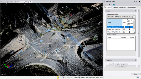
Perform a plane-based registration:
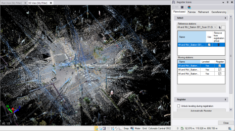
- Select Register Scans in Point Clouds > Registration.
The Register command pane displays with the Plane-based tab selected. The Reference stations drop-down list includes all of the scan stations in the project, with the first one automatically selected and displayed in the list with the Use check box checked by default. The unselected stations are displayed in the Moving stations list with the Register check boxes checked by default.
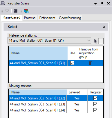
The scan from the selected scan station in the Reference stations list will not move during the automatic registration process. Instead, scans from all of the scan stations in the Moving stations list with a checked Register check box will move to align with the selected reference station's scan.
Notes:
- Because the imported stations do not have position data, the software simply defaults to the first station in the list as the "un-movable" reference station.
- If the scans were registered prior to import, they are displayed together as a single group in the Reference stations list. If the scans are correctly aligned, no additional registration is required. If any of the scans in the group is not correctly aligned, you can click the Remove icon to remove it from the group and then re-register it by clicking the Automatically Register button. In either case, it is recommended that you further refine the registration for higher accuracy as described in "Step 2. Perform an overall registration refinement" later in this topic. - Optionally, do any of the following as applicable:
- Select a different station in the Reference stations drop-down list. Or, click in the selection field located to the right of the list and then click a scan in a graphic view to select that scan's associated station.
- Click the Unlink icon to remove a station from the Reference stations list and add it to the Moving stations list.
- Uncheck the Register check box for any station in the Moving stations list that you do not want to include in the registration process (that is, you do not want them to move).
- If Yes is displayed in the Leveled field for a moving station, it indicates that the station’s leveling status is locked and its vertical axis will not change during registration. This may be the result of the station level status being set to Yes in the field, a previous registration in TBC, or a change to the leveling status in the station’s Properties pane. Optionally, you can check the Unlock leveling during registration check box to unlock the leveling status for all level-locked stations prior to registration, allowing each station's vertical axis to change as necessary. In this case, a warning message is displayed when you click the Automatically Register button identifying the stations whose leveling status will be unlocked. After registration is complete, the Leveled field for those stations will change from Yes to No both in the Moving Stations list and in the Properties pane (where, optionally, you can change it back to Yes).
- Click the Automatically Register button.
The progress of the automatic registration process is displayed in the TBC status bar. When the process is complete, you are prompted to view a Scan Refinement Report. This report lists each station included in the automatic plane-based registration process and the stations to which it is linked as a result. Each station link displays the error, overlap, and confidence values. If successful, the station link background color in the report is green. Otherwise, the background color may be orange or red, indicating lessening degrees of confidence in the results. If this is the case, you might try following the procedure in "To perform a pairwise registration" below.
In the Register Scans command pane, the selected stations in the Moving stations list have moved to the Reference stations list. In addition, the selected reference scan station is now a scan station group and its name in the drop-down list has been appended with each of the added station names, separated by a semicolon (for example: { Selected reference station ; selected moving station 1 ; selected moving station 2 ; selected moving station X}). It is highly recommended that you visually review the resulting point cloud to verify proper alignment of the scans. If you want to georeference the point cloud to survey points, see "To georeference movable station sets" below.
The following example shows a point cloud made up of four scans prior to performing a plane-based registration. Note that all of the station points are on top of each other since they do not include position data, and the various scans do not align properly.
The following example shows the same point cloud after performing a plane-based registration and re-computing project (F4). The station points are now located at their correct positions (relative to each other) and the scans appear to be properly aligned. Also, all of the movable scans are now displayed in the Reference stations list.
Note that in some cases, multiple reference station groups may be created if there is not enough scan overlap to create a single reference station group.
To perform a pairwise scan registration:
If your raw scan data was imported in a format other than Trimble TZF (.tzf) or Faro FLS (.fls), or if it includes both unmovable scan stations (for example, scanning-capable total stations set up on known positions) and movable scan stations (for example free-standing scanners set up on unknown positions), use this workflow to perform a pairwise registration of the scan stations and their associated scans.
This procedure includes two major steps:
- "Step 1. Register station pairs" - In this step, you register all of the movable scan stations with all of the non-movable scanning-capable survey stations, resulting in a single station group.
- "Step 2. Perform an overall registration refinement" - In this step, you perform an overall refinement adjustment to ensure all of the stations in the registered station group are registered (aligned) correctly with each other.
Workflow example:
In this example, which represents a typical pairwise scan registration workflow, you want to register six scans: two scans were collected with a scanning-capable survey instrument set up on known positions (S1 and S2); eight scans were collected with a free-standing scanner set up on unknown positions (Q1 through Q8). When you start the registration process, scan stations S1 and S2 are already combined by default in a station group named { S1 ; S2 }. These stations are fixed and cannot be moved. Next, you will select to register each of the eight movable scan stations with the station group (that is, move their scan points to align with the scan points from stations S1 and S2) using either an automatic registration method or, if that does not provide satisfactory results, by manually selecting matching features in each of the scans to create one or more point pairs that can be used to perform the registration. As you add each movable scan station to the station group, the station group name is appended with each of the station names (for example, { S1 ; S2 ; Q1 ; Q2; Q3...}. When you are done, all of the stations should be included in the same station group.
Note that each time you add a movable station to a station group, the station is registered (aligned) with the entire group, not with each individual station in the group. So, to ensure all of the station scans are registered with each other, not just with a group, you will perform a scan refinement on the final station group to ensure the registration is as precise as possible.
Step 1. Register station pairs
In this step, you will register all of the movable scan stations with all of the non-movable scanning-capable survey stations, resulting in a single station group that can be further refined as described in "Step 2. Perform an overall registration refinement" below.
Note: When you import point cloud data collected with a Trimble SX10, the scale factor in your project is readjusted as necessary. If you have performed a scan registration on existing point cloud data in your project prior to the SX10 import, the registration may be affected by the scale factor change. In this case, you will need to verify the registration and, if necessary, perform a new registration. It is recommended that you always import all point cloud data into your project before performing a scan registration.
- Select Register Scans.
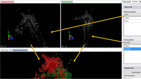
The Register Scans command pane displays with the Pairwise Registration tab selected. Three graphical tab views are also displayed:
- Reference Stations tab - Shows the scan points from the station or station group selected in the Reference stations drop-down list. These are the points that will not move during the registration.
- Moving Stations tab - Shows the scan points from the station or station group selected in the Moving stations drop-down list. These are the points that will move during the registration.
- Registration Results tab - Shows the combined reference (red) and moving (green) scan points. After you perform the registration, the moving scan points should align with the reference scan points.
If your project includes more than one scanning-capable survey station set up on a known position, the stations are automatically included by default in a single station group, which is named by combining each of the individual station names. For example, survey stations 3(S2) and 6(S4) would be automatically included in a group named { 3(S2) ; 6(S4) }. The station group is displayed only in the Reference stations list since it scans are not movable.
- In the Reference stations drop-down list, select a station or station group whose unmovable scan points the moving selection scan points will align during registration. Or, click in the selection field located to the right of the list and then click a scan in a graphic view to select that scan's associated station.
The selected station (or multiple stations if you select a station group) is displayed in the list with a checked Use check box. The scan points for the selected station or station group are displayed on the Reference Scans tab and Registration Results tab (in red).
Note: If your project includes only scan stations set up on unknown points, it is recommended that you select a station near the middle of your scans as your first reference station since it's scan is most likely to overlap with other scans.
- Optionally, in the Reference stations list, do either or both of the following:
- Uncheck the Use check box for a scan station to specify that the station's scan points no longer be displayed in the three registration graphic views and are not used in the registration computation. However, the scan points will move accordingly with the station group.
- Click the Unlink icon to remove a station from the Reference stations list and add it to the Moving stations list.
- In the Moving stations drop-down list, select the station or station group whose scan points you want to align with the scan points from the selected reference station or station group.
The drop-down list includes all scan stations in the project. The list also includes any groups of scan stations that have already been registered with each other.
Your selection is displayed in the list with a checked check box. The scan points for the selected station or station group are displayed on the Moving Stations tab and Registration Results tab (in green).
- Optionally, in the Moving stations list, do either or both of the following:
- Uncheck the Use check box for a scan station as described in step 3.
- Click the Remove icon for a scan station to remove it from the Moving stations list.
Note the following:
- If you select a scan station in the Moving stations drop-down list that includes enabled office-entered coordinates of Survey or Control quality, the station's scan points cannot be moved and the Automatically Register Pair button will not activate. You must do one of the following:
- Change the coordinate status to Enabled as check in the Properties pane (recommended, but will cause error flags to display).
- Change the coordinate status to Disabledin the Properties pane (no error flags will display).
- Make no changes and allow the station's scan points to not be moved (registered).
Note: Optionally, to perform any of these options automatically, select the Refinement tab and click the yellow Resolve Conflicts button to display the Resolve Coordinate Conflicts dialog where you can select the appropriate resolution option.
- If you select a scan station associated with a point that is also associated with a station setup, the point cannot be moved and the Automatically Register Pair button will not activate. You must do one of the following:
- Rename the scan station, resulting in a new movable point being created that is not associated with another station (recommended).
- Delete the conflicting survey scan station (not recommended).
- Make no changes and allow the station's scan points to not be moved (registered).
Next, you will perform an automatic registration, in which the program performs the registration without the need for a manually selected point pair. This is the fastest method to perform a registration and should typically be your first registration choice, but it may not provide satisfactory results, requiring you to use manually selected point pairs instead (as described in step 7).
- Click the Automatically Register Pair button.
A progress bar displays at the bottom of the window showing the progress of the registration computation. When it is complete, the moving scan points should move to a new location (as shown on the Registration Results tab) to more closely align with the reference scan points.
- Check the alignment of the scans on the Registration Results tab.
You can also get some indication of the success of the registration by viewing two key result indicators displayed in the Check Pair section located in the lower portion of the Register Scans command pane:
- Residual error - Displays the residual error and a colored bar representing the tolerance specified for the error.
- Overlap - Displays the overlap percentage and a colored bar representing the tolerance specified for the overlap.
The following tolerance threshold colors are used:
- Red - Does not meet the specified minimal (low) tolerance threshold.
- Orange - Meets the specified minimal (low) tolerance threshold.
- Green - Meets the specified high tolerance threshold.
Optionally, click the Results Display Settings button to change the low- and high-tolerance threshold values.
Note that it is possible to view excellent results on the on the Registration Results tab while obtaining less than excellent results in the Check Pair section. Although you should use both tools to make a determination of success, the results you view on the Registration Results tab is the best indicator.
- Do either of the following:
- If the results displayed on the Registration Results tab show the scans to be at least somewhat closely aligned, click the Optimize Pair Registration button (which further refines the registration) and again review the results. Optionally, click the Optimize Pair Registration button a second or third time to see if you can obtain even better results. When you achieve the most satisfactory results, proceed directly to step 9.
Note: If, after clicking the the Optimize Pair Registration button multiple times, the results stop improving and instead get worse, click the Undo command in Quick Access Toolbar as necessary to return to the most optimal results.
- If the results displayed on the Registration Results tab show the scans to not be somewhat closely aligned, proceed with step 7 in which you will manually select one to three manually selected point pairs to use, along with internal optimization routines, in the registration computation.
- If the results displayed on the Registration Results tab show the scans to be at least somewhat closely aligned, click the Optimize Pair Registration button (which further refines the registration) and again review the results. Optionally, click the Optimize Pair Registration button a second or third time to see if you can obtain even better results. When you achieve the most satisfactory results, proceed directly to step 9.
- To manually select one or more point pairs to use along with internal optimization routines in the registration computation, do the following:
- Ensure the Auto-align check box is checked to provide partial optimization when using the point pair(s) to compute the registration.
In this case, the software will use the point pair(s) you select along with internal optimization routines to perform the registration computation.
- Click in the first cell in the Pick point pairs list. Then, using the cross-hairs cursor, click an observable feature on the Reference Stations tab that is also observable on the Moving Stations tab.
A point labeled 1 displays on the Reference Stations tab. The coordinates for the point display in the first field in the Pick point pairs list. Your cursor automatically advances to the second field.
If it is helpful, click the Center button to center point 1 on the Reference Stations tab.
- Using the cross-hairs cursor, click the same observable feature on the Moving Stations tab.
A progress bar displays at the bottom of the window showing the progress of the registration computation. When it is complete, the moving scan points should move to a new location (as shown on the Registration Results tab) to more closely align with the reference scan points. The results of the registration are displayed in the Check Pair section located in the lower portion of the command pane.
- Click the Optimize Pair Registration button and again review the results. Optionally, click the Optimize pair registration button a second or third time to see if you can obtain even better results. (If necessary, click Undo to return to the most optimal results.)
- Do either of the following:
- If you obtain satisfactory results, proceed directly to step 9.
- If you do not obtain satisfactory results, repeat this procedure to add one or two more (up to three total) additional point pairs. If you obtain satisfactory results, proceed directly to step 9.
If you still do not obtain satisfactory results, you should repeat the manual registration method without using the internal optimization routines. In this case, you will need to select three new point pairs. Proceed with step 8.
- Ensure the Auto-align check box is checked to provide partial optimization when using the point pair(s) to compute the registration.
- To manually select three point pairs to use for a registration computation that does not include the internal optimization routines, do the following:
- Uncheck the Auto-align check box to remove partial optimization when performing the registration computation.
- Select three point pairs as described in step 7. Do not click the Optimize Pair Registration button until after you have created the third point pair.
- After selecting the third point pair, click the Optimize Pair Registration button and review the results. Optionally, click the Optimize Pair Registration button a second or third time to see if you can obtain even better results. (If necessary, click Undo to return to the most optimal results.)
- Proceed to step 9.
- When you have obtained satisfactory results using either the automatic or manual method, click the Add to Reference button to add the selected moving station or station group to the selected reference station or station group.
If you are adding the moving station to an existing single reference station, a new reference station group will be created that includes both station names. For example, if you added station 6(S4) to reference station 3(S2), the new group would be { 3(S2) ; 6(S4) }.
If you are adding the moving station to an existing reference station group, the group name will be appended with the new station. For example, if you added station 8(S6) to a reference station group named { 3(S2) ; 6(S4) }, the new group name would be{ 3(S2) ; 6(S4) , 8(S6) }.
You are now ready to register additional moving stations with the reference station group, adding them to the group name.
Note: The Moving stations list cannot include survey station setups, either individually or as part of a station group, since their scans are not movable.
- Repeat this procedure as necessary until all of the survey and scan stations in your project are included in a single station group.
Note: To remove a station from a station group in the Reference stations or Moving stations list, click its Delete icon, which causes it to return as an individual station to the Reference stations drop-down list (if it is not movable) or both drop-down lists (if it is movable).
Each time you add a movable station to a station group, the station is registered (aligned) with the entire group, not with each individual station in the group. To ensure all of the stations are correctly registered with each other, not just with a group, you must perform the overall registration refinement described in the next procedure.
Step 2. Perform an overall registration refinement
In this procedure, you will perform an overall refinement adjustment to ensure all of the stations in the registered station group are registered (aligned) correctly with each other.
Notes:
- If a station is moved after the refinement, the refined scans will be readjusted as a single block to best fit the station's positions. So although the entire point cloud will move, since it behaves as a rigid entity, the scans will not move in relation to each other.
- You can use the overall refinement process on any registered station groups that were created in the project, imported into the project (already registered), or a combination of both.
- In the Register Scans command pane, select the Overall Refinement tab.
- In the Select drop-down list, select the registered station group you want to refine.
The stations included in the group are displayed in the list beneath it.
- Check the Fixed check box for each station whose scan you do not want to move during the refinement.
The non-checked stations will align to the fixed stations during the refinement process.
If a station is is set up on a known location, the check box is checked by default and cannot be unchecked.
At least one station must be specified as fixed to perform the refinement process, even if the station is not set up on a known location.
- Check the Include check box for each station you want to include in the refinement process.
If Yes is displayed in the Leveled field for a station, it indicates that the station’s leveling status is locked and its vertical axis will not change during refinement. This may be the result of the station level status being set to Yes in the field, a previous registration in TBC, or a change to the leveling status in the station’s Properties pane. Optionally, you can check the Unlock leveling during refinement check box to unlock the leveling status for all unfixed level-locked stations prior to refinement, allowing each unfixed station's vertical axis to change as necessary. In this case, a warning message is displayed when you click the Refine Overall Registration button identifying the stations whose leveling status will be unlocked. After refinement is complete, the Leveled field for those stations will change from Yes to No both in the Stations list on the Refinement tab and in the Properties pane (where, optionally, you can change it back to Yes).
Note: If you check the Fixed check box for a station, its position and orientation will not change regardless of its leveling status or whether the Unlock leveling during refinement check box is checked.
- Click the Refine Overall Registration button to start the refinement process.
A progress bar displays at the bottom of the window showing the progress of the refinement computation. When it is complete, the Project Scan Refinement Report displays on a new tab. It includes the project file data, coordinate system information, reference stations included in the refinement, overall results, and results by station group.
This completes the registration and refinement process. If your station group is movable and you want to georeference it to known survey points, proceed with the next section.
To georeference movable station groups:
If your station group is movable (it does not include scans from survey stations set up on known positions), you can georeference it to survey points with known positions. One or more georeference point pairs can be selected to perform the transformation:
- One point pair - The data will be translated (moved) only.
- Two point pairs - The best transformation that keeps the Z axis unchanged will be used.
- Three or more point pairs - The best transformation based on all point pairs will be used. If the scan or group was leveled, the resulting transformation will be constrained in the Z axis.
Note for Trimble Perspective users: Georeferencing of scans and control points performed in Trimble Perspective is not as accurate as it could be because the scans are ground-scaled while the control points are grid-scaled. When you georeference scans in TBC, the point cloud is scaled to grid to ensure the georeferencing is as accurate as possible. Therefore, if a message displays alerting you to excessive errors in the georeferencing performed in the field software, it is recommend that you perform georeferencing in TBC as described here.
- In the Register Scans command pane, select the Georeferencing tab.
- In the Select drop-down list, select the movable station group you want to georeference.
The stations included in the group are displayed in the list beneath it.
If you are working with imported scan data that includes one or more control points and survey-quality, scanner-based laser observations of those points (for example, Trimble X7 scanner data collected with Trimble Perspective field software), the Generate Pairs button and Georeferencing automatically check box are enabled. Proceed with step 3. Otherwise, go directly to step 4.
Note: A laser observation is considered linked to a control point when both were assigned the same name in Perspective. These are referred to as "imported" point pairs.
- If you are working with imported point pairs, do either of the following
- To display imported point pairs in the Define Transformation list, click the Generate Pairs button.
For each imported point pair, the coordinate for the control point and the coordinate for the corresponding observation are displayed in editable fields. Residual values that would result from georeferencing are also displayed for your review before proceeding. If necessary, change the coordinate in any of the fields by entering or selecting a different coordinate. Or, click the Delete button to remove an imported point pair from the Define Transformation list so that it is not used for georeferencing.
If applicable, proceed to step 4 to manually add additional point pairs to the list. Otherwise, go directly to step 6.
- To automatically perform georeferencing using imported point pairs with no additional input (that is, you do not need to edit coordinates or manually add additional point pairs to the list), check the Automatic check box. Then press F4 to compute the project. Movable scans are transformed accordingly.
When you check the Automatic check box, the Backsight property displayed in the Properties pane for the imported scan observations changes from No to Yes. Just as total station backsight observations can be used to compute a total station resection, backsight scan observations are used to georeference a group of point cloud stations.
Note: This option eliminates the need for subjective point selection, resulting in more consistent results.
- To display imported point pairs in the Define Transformation list, click the Generate Pairs button.
- To manually add point pairs to the Define Transformation list:
- Click in the Point ID field, and then select in a graphic view or the Project Explorer the survey control point to which you want to georeference the scan. Or, type in the point ID.
- Click in the Scan point field, and then select in a graphic view the observable feature in the scan you want to georeference to the selected survey control point.
The nearest scan point will be selected.
- Optionally, create additional point pairs to use for georeferencing.
After you enter a second point pair, residual values that would result from georeferencing are displayed for each point pair based on your selections.
Note that you can select to exclude any point pair from being used for georeferencing by unchecking its check box. Or, click its Delete button to remove it altogether.
- When you are done selecting point pairs, click the Georeference button.
The georeferencing process completes and the project is automatically computed. Movable scans are transformed accordingly.
- If necessary, repeat to georeference additional movable scans or station groups.
Note: Point clouds scans that were registered prior to or after import will scale correctly (the appropriate scale factor is applied) when they are georeferenced to a new location or the coordinate system specified for the project is changed.
