Adjust a Network
Adjust your network or subnetworks (two or more networks in your project with unconnected observations) after you have processed the baselines and reviewed the GNSS Loop Closure Results report to ensure the quality of your project.
You must fix at least one point horizontally and one point vertically to do a least squares adjustment. They do not have to be the same point, and the horizontal fix can be either latitude and longitude, or northing and easting. If you have control quality elevation and height for the same point, you can fix only one or the other (or neither). You cannot fix elevations for GNSS points unless you have a coordinate system with a geoid defined. With no geoid model, you can only fix a height. You can add new control coordinates and disable observations with the Adjust Network command open.
You can also fix azimuth/bearing and/or horizontal distances for the adjustment.
Notes:
- If you adjust a network and then make a change that requires that your project be recomputed, the Compute Project Needed indicator displays in the status bar and a message displays asking whether you want to keep or clear the network adjustment. This allows you to make the best decision based on your workflow. However, be aware that if you choose to keep the network adjustment after you have made changes, the adjustment results may no longer be applicable to your project. You should consider performing a new network adjustment after you have completed your changes.
- The Adjust Network command allows you to perform a network adjustment that includes two or more subnetworks (networks with unconnected observations) within your project. You can specify adjustment parameters for each subnetwork individually as necessary before all subnetworks are adjusted together. An individual adjustment report is generated for each subnetwork. See steps below.
To adjust a network:
- Select Adjust Network in Survey > Network.
The Adjust Network dialog displays.
A subnetwork detection is performed automatically when the Adjust Network command is run. If there are subnetworks in the project, a new drop-down displays at the top of the command pane, allowing you to select the subnetwork with which you want to work. The selected subnetwork is highlighted in the Plan View. If there is only one network, the drop-down list does not display.
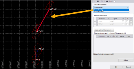
- If applicable, select the subnetwork for which you want to set adjustment parameters in the Subnetwork name drop-down list.
The parameters you specify in the next several steps pertain only to the select subnetwork. You can repeat them for each subsequent subnetwork to be included in the overall adjustment.
The Constraints tab includes two major sections. The top section allows you to fix control quality coordinates for the adjustment. The lower section allows you to optionally specify azimuths and horizontal distance constraints for the adjustment.
Note: Adjust Network computes final points using only vectors in an "enabled" state.
- To fix a horizontal or vertical coordinate in the network, check its 2D, h (ellipsoid height), and/or e (elevation) check box in the Fixed Coordinates table.
Coordinate fixes that are not possible are unavailable. To add another coordinate to the network, use the Add Coordinate command. (The Fixed Coordinates table is populated in real-time; you can leave the command pane open, and it will update as you add control coordinates to your project.)
- To fix an azimuth/bearing and/or horizontal distance in the network, do the following:
- Select the appropriate constraint type in the Add Azimuth/Bearing Constraint / Add Horizontal Distance Constraint drop-down list.
An editable row displays in the Fixed Azimuths/Bearings and Horizontal Distances table.
- Click in the From Point field and then use the Plan View to select the point from which the azimuth/bearing or horizontal distance will be fixed.
- Click in the To Point field and then use the Plan View to select the point to which the azimuth/bearing or horizontal distance will be fixed.
When you tab off the To Point field or click in the Value field, the computed azimuth/bearing or horizontal distance is displayed.
- If necessary, enter a new azimuth/bearing or horizontal distance in the Value field.
- Click the Expand icon at the beginning of the row to display the standard error for the azimuth/bearing or horizontal distance. If necessary,change this value.
Note that you can deselect the Fixed check box if you decide to keep a defined constraint but do not want use it in the adjustment.
- Repeat these steps to add additional azimuth/bearing and/or horizontal distance constraints for the adjustment.
To remove a constraint, click the Delete icon at the end of the row in the table.
Note: If your network or subnetwork includes GNSS data, you can minimize error flags that might result from an adjustment using these constraints by selecting Project Settings > Network Adjustment > Transformations and ensuring the GNSS: Compute azimuth rotation and GNSS: Compute scale factor options are set to Yes, which are the default settings.
- Select the appropriate constraint type in the Add Azimuth/Bearing Constraint / Add Horizontal Distance Constraint drop-down list.
- Click .
An adjustment is performed on the network, or all subnetworks, using the specified constraints.
If you are adjusting subnetworks, only the points within each subnetwork are used in the adjustment.
The status of the adjustment displays above the Adjust button, and the Results tab appears. Error ellipses (if any) appear in graphic views, showing the magnitude and direction of point errors.
Note: If you have unresolved computation errors, revisit the Baseline Processing Report or Flags pane, and resolve or disable problematic baselines before adjusting the network.
Optionally, to adjust the start azimuth in a traverse, in Project Explorer expand the start point of the traverse. Double-click the Azimuth property to open the Properties pane. Under Point information, use the Quality drop-down menu to select the azimuth quality.
- Control Quality - The azimuth will not be corrected. Set the azimuth deviation tolerance in Computation Settings.
- Survey Quality - The azimuth will not be corrected.
- Mapping Quality - The azimuth will not be corrected.
- Unknown Quality - The azimuth will be corrected using the control points.
- Click the Results tab to view the status of the adjustment.
- Pick points and vectors in a graphic view or the Project Explorer to review their errors and residuals in the Results tab.
You can select a subset of the results in the drop-down list below the results summary.
- For details, click the Network Adjustment Report icon on the command pane's toolbar to display the Network Adjustment Results report(s) in your default Web browser.
If you are adjusting subnetworks, a separate report is created for each subnetwork.
- To set the error estimate scalars for the next adjustment based on the reference factor from the previous adjustment, click the Weighting tab.
Scalar boxes are available for what is enabled in your project.
- Type a value to multiply by in each of the Scalar boxes, as needed. The goal is to get the Reference Factor to 1.00.
- Click the
 icon. In each variance group, the reference factor from the last network adjustment is multiplied by the scalar; the new value appears in the Scalar box.
 - Click again.
Repeat the above steps as necessary until the adjustment results are satisfactory for the network or subnetworks.
Note: To clear all of the current adjustment results, click the Clear Adjustment Results icon in the command pane toolbar
- When you are done, click to save the network adjustment results to your project.
Caution: If you exit the command without clicking , the adjustment results are not saved.
To exit the command without performing an adjustment or without saving the adjustment results, click . After network adjustment completes, points that were adjusted are marked Adjusted in the Project Explorer, and are marked with an
 icon in the plan view and Properties pane.
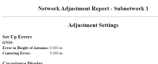
 - Optionally, click the Network Adjustment Report icon in the command pane toolbar to generate an Adjust Network Report to review successful adjustment statistics, such as the adjusted grid and geodetic coordinates, adjusted observations, and covariance terms.
You can also use the report to review error ellipse and residual details to determine which vectors need to be disabled, how control points should be fixed, and which settings may need to be changed before re-adjusting the network. And you can view computed values for the transformation parameters of GNSS vectors.
If you are working with subnetworks, each subnetwork report is displayed individually on a separate tab in your browser.
Note: Read-only vector transformation parameters are displayed in Project Settings > Coordinate System > Network Adjustment Transformation.
To clear a network adjustment:
Select Clear Adjustment Results in Survey > Network.
