Computation Settings
Use Computations settings to:
- Specify whether to use a single observation or the weighted mean of all observations to calculate the position for each sideshot point. If you select to use a weighted mean, each observation is weighted based on its length (shorter observations have more weight than longer observations).
- Review and set horizontal and vertical tolerances for computed survey data, including points of varying quality, and meaned GNSS vectors.
Note: If computation results on data fall outside these tolerances, the data is flagged in the Project Explorer and graphic views, and a message appears in the Flags pane.
- Select a level of confidence for displayed error values.
- Specify the horizontal and vertical tolerances to enforce when creating surface breaklines from 3D alignments.
- Specify the horizontal and vertical tolerances for as-staked points when compared to their corresponding design points.
- Specify the horizontal and vertical tolerances, maximum angle misclosures, minimum horizontal and vertical precisions, and whether a weighted means should be used when performing traverse adjustments.
- Set the maximum edge length and angle defaults for creating surface triangles.
- Set the default distance from which you want to view registered images in the Station View.
To access the settings:
- Select Project Settings in the Quick Access Toolbar.
The Project Settings dialog displays.
- Click Computations in the left pane.
|
Computation Settings |
||
| Sideshot computations |
Select how you want the position for each sideshot to be calculated:
If you select to use a weighted mean, each observation is weighted based on its length (shorter observations have more weight than longer observations). |
|
| Sea level correction |
Select whether you want to reduce all terrestrial observations to the ellipsoid. For a scale-only survey at elevation, select No. For mixed data types, and projects using projections that are at the ellipsoid, select Yes. |
|
|
Point Tolerances |
||
| Survey Quality Mapping Quality Unknown Quality |
For each of these quality types, specify the horizontal and vertical tolerances for the comparison between the final computed coordinates for a point and the coordinates computed using other data. An out-of-tolerance flag displays for any point with the assigned quality that exceeds one of these tolerance values. |
|
| Merge on Import |
Select the rule you want to apply when you are merging points on import that have the same name. By Point Tolerance x3 - Merge the points if their positions are within three times the specified quality point tolerance in Project Settings (see above). By Point Tolerance - Merge the points if their positions are within the specified quality point tolerance in Project Settings (see above). By Custom Tolerance - Merge the points if their positions are within the point tolerance specified in the fields located beneath the Merge options drop-down. By Station Point - Merge the points if one of them is a station point, regardless of their positions. |
|
|
GNSS Vector |
||
| Tolerance of Meaned Vectors |
Specify the tolerance for comparison between the horizontal and vertical components of the meaned vector and the horizontal and vertical components of the individual vectors between two points. An out-of-tolerance flag displays with any vector that exceeds this tolerance value. |
|
| Point Coordinates |
Select whether to use time-dependent transformations when computing end-point coordinates for a vector. Select the Coordinate Reference System (CRS) in which vector coordinates are displayed and exported:
Note: Exporting vectors in the International Terrestrial Reference System (ITRS) at the measurement epoch may be required to perform a network adjustment in third-party software expecting vector coordinates in this Coordinate Reference System. |
|
|
Device Orientation |
||
| General: Tilt distance tolerance |
Specify the tolerance for the tilt distance of an instrument during a fixed measurement. An out-of-tolerance flag displays with any observation whose related instrument tilt exceeds this tolerance value. |
|
| General: Magnetic declination |
Specify the angle between magnetic north and true north. To obtain the angle between magnetic north and grid north, the meridian convergence angle must be added to the magnetic declination. |
|
| Total Station: Reorientation tolerance |
For each time a total station was reoriented in the field (for example, the instrument orientation was disturbed), TBC compares the new orientation angle with the first one recorded. If a difference is detected that exceeds the value specified here, a warning flag is displayed with the total station. In this case, it is recommended that you review the orientation property for each backbearing to identify and correct the problem (for example, disable one or more backsights), helping to ensure the accuracy of subsequent foresight observations. |
|
| Total Station: Azimuth deviation tolerance |
Specify the tolerance for the azimuth deviation when adjusting traverses. The azimuth from the observation is compared to the azimuth determined by the control points along the traverse. The tolerance value has two roles. First, it determines if an azimuth with unknown quality should be corrected. Second, it determines if an azimuth with control quality is out of tolerance. An out-of-tolerance flag displays with any observation whose azimuth exceeds this tolerance value. |
|
|
Mean Angles |
||
| Horizontal angle |
An angular or slope distance tolerance for a mean turned angle is a quality control setting used to ensure the consistency of repeated measurements.These tolerances can vary depending on the requirements of the project or organizational standards. Generally, in surveying and construction, the tolerance is determined by the precision required for the project. For high-precision work, the tolerance might be very small, such as a few seconds of arc, while for less critical work, it might be larger. The tolerance for the comparison between the horizontal angle of an observation and the mean horizontal angle of the mean turned angle (MTA). |
|
| Vertical angle |
Tolerance for the comparison between the vertical angle of an observation and the mean vertical angle of the MTA. |
|
| Slope distance |
Tolerance for the comparison between the slope distance of an observation and the mean slope distance of the MTA. |
|
|
Photogrammetry |
||
| Point Intersection: Horizontal tolerance Vertical tolerance |
Specify the tolerances for horizontal and vertical angles between photogrammetry observations and computed points. An out-of-tolerance flag displays with any computed point whose angle exceeds these tolerance values. |
|
| Intersection: Maximum strength of figure |
Specify the maximum strength-of-figure value for a computed point. An out-of-tolerance flag displays with any computed point whose maximum strength-of-figure exceeds this value. |
|
| Station Resection: Horizontal tolerance Vertical tolerance |
Specify the tolerances for horizontal and vertical angles between photogrammetry observations and resected points. An out-of-tolerance flag displays with any resected point whose angle exceeds these tolerance values. |
|
| Station Resection: Maximum strength of figure |
Specify the maximum strength-of-figure value for a resected point. An out-of-tolerance flag displays with any resected point whose maximum strength-of-figure exceeds this tolerance value. |
|
|
Traverse |
||
| Manual horizontal tolerance Manual vertical tolerance |
Specify the maximum horizontal and vertical tolerance to determine when manually adjusted traverses should be re-computed. This is done by computing temporary coordinates as though the traverse were automatically computed and comparing them to the current manually adjusted values. |
|
| Maximum angle misclosure per station |
Specify the maximum angle misclosure, which is this number multiplied by the number of stations in the traverse. |
|
| Minimum horizontal precision Minimum vertical precision |
Specify the minimum horizontal and vertical precisions. The minimum horizontal precision is the ratio of the traverse length to the horizontal misclosure. The minimum vertical precision is the ratio of the traverse length to the vertical misclosure. |
|
| Use weighted mean |
Select Yes to specify that each observation and its reciprocal observation are combined with a weighted mean, which is proportional to the number of individual observations. Select No to specify that observations are combined with a simple mean. |
|
|
COGO |
||
| Parcel: Minimum precision |
Precision is the ratio of the parcel's perimeter distance divided by the sum of the misclosures. When creating parcels using the Create COGO command, parcels with precisions less than this threshold will be flagged as out-of-tolerance. |
|
|
Corridor |
||
| Maximum sampling distance |
Enter a maximum sampling distance for the corridor. This setting is essential when you create corridors and export corridor data. Note: Before exporting corridor data, it is recommended that you set the maximum sampling distance to less than 5 m. Setting the maximum distance to less than 5m ensures higher accuracy in your export file. |
|
| Surface edge angle |
When using a surface instruction in a corridor, extra cross-sections are inserted when the surface boundary has deflections larger than this angle. |
|
| Save Linework |
Set this to Yes to automatically save corridor breaklines as linestrings (and a separate node under the corridor surface in the Project Explorer) when you create a corridor surface. For details, see Extract Linework from a Corridor Surface. Note: When sending corridor design data to the field, it is often necessary to have the breaklines of the corridor surface to export with the surface data. |
|
| Boring log discovery tolerance |
Specify the distance within which boring logs will be grouped and used to calculate strata at a preceding station. To determine strata for a particular station, the next upstation boring log is found. Any subsequent upstation boring log that is within the discovery tolerance is added to the group of preceding, grouped boring logs to calculate/interpolate the strata for the aforementioned station. |
|
| Boring log max offset |
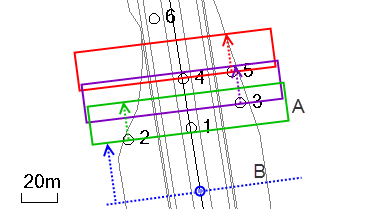
Specify the distance on either side of an alignment within which boring logs are allowed to be created; if they are already created and you change this setting, it specifies the perpendicular distance from the alignment within which boring logs will be used to calculate strata at the station. (B in the image below)
In this example, the alignment travels from south to north. The blue dot indicates the station for which corridor strata is being calculated/interpolated. From that station, the program searches up the alignment (dashed blue arrow) for a boring log within the max offset (blue perpendicular dashed line). When boring log 2 is discovered, the discovery tolerance (20 m in this case) is applied (green box) up the alignment to group it with boring logs 1 and 3. From boring log 3 (the furthest in the group) the discover tolerance is applied again (purple box) to add boring logs 4 and 5 to the group. The tolerance is then applied again (red box) from boring log 5, but no further boring logs are discovered (boring log 6 will not be used in calculating strata because it is not within tolerance). For more information and examples, see Understanding Corridor Strata in the help. |
|
| Honor sign of the slope |
When set to true, negative cut and fill slopes are honored when creating side slopes. Note: If you are unable to tie a corridor side slope instruction to the original ground (OG) surface when a transition is required between cut and fill conditions, TBC might be restricting the side slope instruction based on the sign of the slope value relative to the vertical position of the tie-in point. This issue can, for example, occurs in a corridor where the tie-in point is consistently under the OG reference surface (the side slope instruction is only applying a cut slope because the tie-in point is below the OG surface. Cut slopes are restricted to positive slope values. Using a negative slope value with a cut instruction will not work. To tie the corridor back up to the OG surface when the tie-in point is under the OG, a fill slope is technically required (which uses negative slope values). This restriction prevents the design from handling standard cut-to-fill transitions required by superelevation or varying terrain, as the instruction cannot automatically switch between requiring a positive (cut) and a negative (fill) slope based on the geometry. You are 'stuck' and cannot complete the corridor design by tying it to the OG. Change this setting to true to allow a single side slope instruction to handle the transition from cut to fill (or fll to cut) dynamically, based on the vertical position relative to the OG surface. |
|
| Pre-clip section line |
Adjust the left/right extents by clipping the section line to the surface boundary prior to slicing the surface. This can result in faster slicing in some cases. |
|
|
Drill Plan |
||
|
|
See Drill Plan Settings. |
|
|
Mass Haul |
||
| Site connection tolerance |
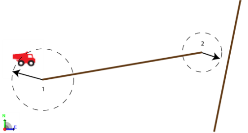
Enter the maximum planimetric distance within which earthwork sites will be considered as connected to haul roads, even if there is a gap (less than the tolerance) between them. Any haul roads that start or finish within this distance to the earthwork site will be considered joined.
Figure: Site and haul road connection tolerances These settings are essential when you are creating earthwork sites or haul roads for use in a site mass haul analysis or a corridor mass haul analysis. |
|
| Haul road connection tolerance |
Enter the maximum planimetric distance within which haul roads will be considered as connected to other haul roads, even if there is a gap (less than the tolerance) between them. Any haul roads that start or finish within this distance to other haul roads will be considered joined. |
|
| Earthwork site size |
The size of each side of a hexagon used to depict each earthwork site. |
|
|
Piling |
||
| Default pile length |
Specify the default length to be used for piles of any type. This value and the one below are used when you create pile types, unless you change them for a specific type of pile. |
|
| Default material name |
Name the material to be used for piles of any type. |
|
| Expected embedment length |
Specify the default distance that piles of any type intended to be driven into the ground. These settings (this one and the next six) are essential for determining whether individual as-built piles pass or fail when you run a Piling Quality Report. |
|
| Minimum embedment length |
Specify the default minimum acceptable distance that piles of any type must be driven into the ground. |
|
| Blow count interval |
Specify the maximum distance a pile can move (interval distance) within a specified series of hammer strikes (target blows). These settings are essential for determining whether individual as-built piles pass or fail when you run a Blow Count Report. |
|
| Blow count number (target blows) |
Specify the number of blows of the pile hammer in the blow count interval, counted throughout the placement of the pile. (See also blow count requirement.) |
|
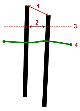
| 2D positional tolerance |
Specify the maximum allowable planimetric distance (2) that the coordinates of a planned and its associated as-built pile can be from each other (as measured in a horizontal plane from the cutoff elevation of the planned pile to the plane's intersection with the as-built pile).
Figure: 2D and 3D piling tolerances These tolerances are essential for determining whether as-built piles pass or fail when you run a Piling Quality Report. |
|
| 3D positional tolerance |
Specify the maximum allowable distance (1 above) in 3D space that the cutoff coordinates (for the top of pile) of a planned pile and its associated as-built pile can be from each other. |
|
| Inclination tolerance |
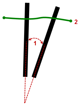
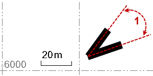
Specify the maximum allowable difference (1) in vertical angle degrees between a planned pile and its associated as-built pile.
Figure: Piling inclination tolerance |
|
| Rotation (inclination orientation) tolerance |
Specify the maximum allowable difference (1) in the planimetric bearing of the pile's orientation.
Figure: Piling orientation tolerance |
|
| Pile penetration rate |
Estimate the average rate (in meters or feet per hour) at which piles of any type can be embedded (how quickly can piles be hammered into the ground?). These estimations are essential for predicting total rates and costs when you run a Piling Quality Report. |
|
| Charge out rate |
Estimate the average price (in local monetary units per embedment distance unit (m/ft)) that you/the piling contractor will charge the customer to perform piling work on this job. |
|
| Machine cost |
Estimate the average cost (in local monetary units per hour) to you/the piling contractor to rent and/or operate a piling rig on this job. |
|
| Fuel cost |
Estimate the average fuel cost (in local monetary units per hour) to you/the piling contractor when running a piling rig on this job. |
|
| Operator cost |
Estimate the average cost (in local monetary units per hour) to you/the piling contractor to pay the operator of the piling rig on this job. |
|
| Navigation time per pile |
Estimate the average time (in decimal hours) the piling rig will take to navigate between each pile location on this job. |
|
| Efficiency factor |
Apply a factor to the overall cost per hour estimates to account for any real-world variables that might affect efficiency. Positive factors (e.g., 1.2) mean that the project has been positively affected/achieved greater efficiency; negative factors (e.g., 0.8) mean that the job has achieved lower efficiency. |
|
|
Road Intersection |
||
| Maximum elevation difference |
The elevation of alignments cannot differ more than this value to make a valid intersection point. |
|
| Minimum/Maximum elevation of highway overpass |
The elevation difference that determines if a highway interchange is an overpass must fall between this min and max. To make it possible to pass under, the overpass elevation difference should be 7 - 14 m (23 - 46'). |
|
| Maximumdifference horizontal |
This constant is related to the case of multiple alignments intersecting at (almost) the same point. When intersection points are closer than this from each other, they are considered as one intersection. |
|
| Maximum distance for twin |
The largest possible distance between two intersection points to form a twin intersection. When using the Add Joint command's Automatic method option, a twin intersection with a joint is created when a second intersection is created near an existing intersection, where the shared leg is shorter than this Maximum distance for twin setting. |
|
| Minimum length of leg |
Minimum length to activate leg The minimum length will depend on combinations of other properties, but cannot be shorter than the automatically minimized length of the leg. See Intersection Leg Properties. |
|
| Vertical modus |
Defines whether the vertical linework is an arc or a parabola. |
|
| Maximum vertical grade |
Maximum vertical grade for vertical turning methods The maximum grade is set to 8 % in the grade check method. See Intersection Connection Properties for details. |
|
| Maximum transition rate (angular) |
Maximum value for rthe change of slope in linear slope transition method. The unit is angle per meter. |
|
| Smoothing length |
The length of S-curve that is fitted in road intersection linestrings to smooth out angle distances. |
|
| Max segment length |
Maximum segment length to use when intersection linestrings are used in a surface. |
|
| Ramp alignment side |
Defines the side of the alignment of the ramp. See Create and Edit a Corridor Interchange Ramp for details. |
|
|
Surface |
||
| Minimum warning distance |
Enter the shortest distance between a surface and any rejected vertex, breakline, or drapeline for which you want a warning flag to display. Note: This setting is essential when you use an alignment in the creation of a surface; with warning flags you can better constrain the resulting breakline's horizontal and vertical distance from the alignment. |
|
| Slope arrow length |
Select Yes to see the slope direction of each triangle of surfaces that you create. Surface triangles with a diamond (instead of an arrow) have a slope of zero. To specify the length of the slope arrows, select Project Settings > Computations > Surface> General. Change the value in the Slope arrow length box. Slope arrows are essential when you check an imported surface or create a new one. Note: To see the slope direction of each triangle in a surface, set Slope arrows to Show in the properties for a surface.
|
|
| Volume computation |
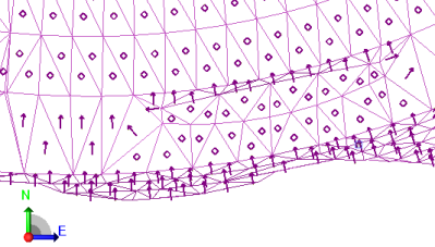
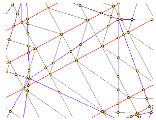
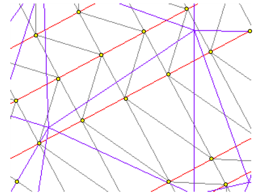
Select a method used compute a difference model when calculating the volume differences between two surfaces/to intersect the two surfaces used to compute the difference model:
Note: Although this option results in the most accurate isochore, it takes longer to compute and may result in many unnecessary vertices. Example: Existing ground surface triangles are shown in purple. Finished design triangles are shown in gray and red (breaklines). Yellow dots indicate the isochore vertices that are created at each intersection and overlap point between the two surfaces.
Figure: Isochore computation method - Track All Triangles
Figure: Isochore computation method - Track All Triangles (cross-section)
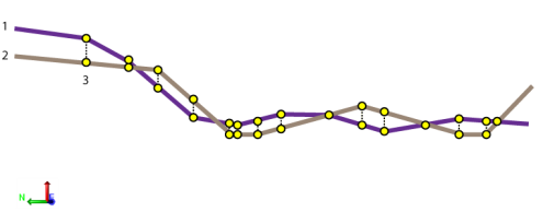
Figure: Isochore computation method - Track Finish Breaklines Note: This method can be set for other calculated isochores, not just cut/fill maps. When computing a topsoil stripping surface, non-breakline triangle edges that cross the offset line are included in the formation of the new surface, unless the Volume computation project setting is set to Track Finish Breaklines (in Project > Project Settings > Computations > Surface> General). The additional points that are created improve the depth consistency of the new surface at the expense of slowing the calculations. Do not track breaklines - Select this to compute the difference model without creating additional intersection points from the breaklines. Note: Use this setting when you are using point cloud data or imported ttm files and you do not need the extra precision of computing intersections due to the breaklines. This is the fastest option and creates the least amount of data. |
|
| Horizontal tolerance Vertical tolerance |
Enter the maximum elevation differences by which the breakline approximation of a 3D alignment can deviate from its actual vertical alignment. |
|
| Maximum sampling distance |
Enter a maximum sampling distance for the surface. This setting is essential when the surface is associated with an alignment, and you set the Alignment-based property for the surface to Yes. |
|
| Maximum edge length |
This shows the maximum triangle edge length allowed on new surfaces. Tip: This setting and the one below can reduce the amount of trimming needed on a surface's edge when you create a new surface. |
|
| Maximum edge angle |
This shows the maximum outer angle allowed at vertices on this surface's edge as defined in Project Settings. Type a new angle. |
|
| Adjust 'flat' triangles |
Select Yes to adjust triangles to remove 'flat' triangles from contour source data. |
|
| Tolerance |
This shows the distance within which duplicate vertices will be moved to prevent 'flat' triangles from forming. |
|
| Difference surface name |
Type the name for the difference model that is created when you compare two surfaces. This setting is essential when you run an Earthwork Report. |
|
| Allow blocks in surface |
Select Yes to allow CAD blocks to be used as members in the formation of surfaces. |
|
| Duplicate point tolerance |
Specify whether points in the same relative location are duplicates based on the horizontal distance between them. Using this tolerance, duplicate points in some imported file formats are retained or removed in the resulting surfaces. This applies only to internal data in imported TTM, LandXML, and other types of "fixed" surfaces, which can affect how surface triangles are formed. Once a surface is imported, this tolerance cannot be changed (for the imported surface). |
|
| Elevation template Cut depth template Fill depth template Remnant depth template Remnant fill depth template |
Use these templates to specify the abbreviations you want to see next to cut and fill values in cut/fill map grids and elevations in surface elevation grids. You can also control where the abbreviation is positioned in relation to the calculated value. For example, at a calculated elevation of 10.9 on a surface elevation grid:
These settings are essential when you create cut/fill maps and when you create surface elevation grids. |
|
| Above design grade tolerance Below design grade tolerance |
Specify the tolerance within which the completed surface can be left above and/or below the design elevation. |
|
| Label color |
Specify default colors for cut, fill, and at grade (zero) text labels. |
|
| Shading cut color |
Specify default colors for cut, fill, and at grade (zero) areas. |
|
| Zero area tolerance |
The maximum delta elevation of a triangle corner for the triangle to be considered 'on-grade' (for reports). |
|
|
Takeoff |
||
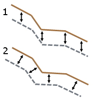
| Topsoil offset method |
Select an option for how to offset the topsoil boundary when calculating volumes to strip:
Figure: Vertical vs. perpendicular offset These settings are essential when you define topsoil stripping and replacement areas in preparation for running a Takeoff Report. Note: Selecting Perpendicular as the offset method will result in greater topsoil volumes, since it applies the thickness to the slope area of the surface. Selecting Vertical applies the thickness to the horizontal area of the surface. |
|
| Gap closure tolerance |
This shows the distance that lines will be extended to close unintended gaps when site improvement areas are being created within closed shapes in the Assign Site Improvements command. |
|
|
As-Staked Points |
||
| Horizontal tolerance Vertical tolerance |
Specify the tolerances for horizontal and vertical distances of as-staked points from their corresponding design points. An out-of-tolerance flag displays with any as-staked point that exceeds these tolerance values. |
|
| Flag vertical out of tolerance |
Specify whether to display out-of-tolerance flags with as-staked points whose vertical tolerances are exceeded. |
|
|
Field Data |
||
| Protect site calibration files Protect for control points files Protect other site files and external designs (site files include site units, site map objects, avoidance zones, and feature code files)
|
Select Yes for any of these settings to prevent yourself or others from overwriting the job site data in a data synchronization area (and ultimately on assigned controllers) with the job site data in your project. Accidentally overwriting files in your data synchronization area usually occurs when you add an external job site or external design to your project. When you or other users try to save site data to a controller that already has those types of files, you will be prevented from doing so. These settings are essential when you add or edit job site data, resolve conflicts in job site data, and import external job site data. |
|