Create COGO Collections and Compute Parcels
Use the Create COGO command to create a COGO (COordinate GeOmetry) collection of points and lines in your project that you can, optionally, use to create cadastral parcels and compute parcel closure.
For example, while referring to boundary line data in a printed drawing format (for example, bearings and distances on a plot map), you can manually enter simple COGO point and line commands quickly and efficiently using just the keyboard or numeric keypad; or use the available easy-to-use interface controls. As you enter each COGO command, the point or line is automatically drawn in the Plan View.
Or, if your project already contains boundary CAD linework, you can use the linework to automatically create a COGO collection.
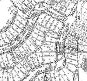
Following is an example of a drawing that might be used as input to manually create COGO lines and parcels in TBC.
Note: Although you can create just COGO points in this command, you cannot create COGO parcels when there is no closed linework; you must have closed linework to create parcels.
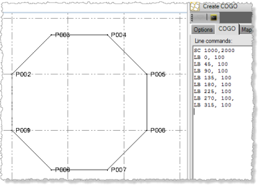
Each COGO command you enter manually must begin with a command code followed by one or more required values. The following example shows a flat octagon shape created with nine commands. The first command is the Start Coordinate - SC command (represented by the code SC), which includes two coordinate values defining the start of the linework. The next eight lines are Line by Bearing/Azimuth - LB commands (represented by the code LB), each specifying a subsequent bearing/azimuth and length value.
There are five types of COGO commands:
- Start - Use one of these commands to define a starting coordinate, point, or by offset for a line.
- End - Use one of these commands to end a line at a measured point or coordinate that is fixed in the adjustment computation. These commands are typically used when performing a Grant Boundary adjustment on a parcel that has already been computed.
- Add Point - Use one of these commands to define a point based on one or more coordinates/points, distances, azimuths, lengths, and/or northing and easting.
- Add Line - Use one of these commands to define a line based on a coordinate/azimuth, points, an angle, or a line extension.
- Add Arc - Use one of these commands to define an arc based on a coordinate/azimuth, radius deflection angle, interior angle, tangential angle, or angle extension.
- Sideshot Mode - Use one of these commands to define one or more radial sideshots (single-segment lines originating from the current point) or extended sideshots (multi-segment lines originating from the current point).
To see a description of all of the COGO command codes, see COGO Point and Line Commands.
This topic includes the following procedures:
- "Step 1. Create a new COGO collection"
- "Step 2a. Create COGO linework manually from paper-based data"
- "Step 2b. Create COGO linework automatically from existing project linework"
- "Step 3. Create parcels and compute parcel closure (Optional)"
- "Edit an existing COGO collection"
Prerequisites:
See the Subscription Plans page. For a license matrix by command, see the License page in the TBC Community. Also see View and manage licensed features.
Step 1. Create a new COGO collection
- Select Create COGO in Survey > COGO to display the Create COGO command pane.
- On the Options tab, do one of the following:
- If no COGO collections exist in the project, enter a name for the new COGO collection in the Collection name field and click the Create button.
- If one or more COGO collections already exist in the project, select <Create COGO Collection> in the Collection name drop-down list. Then enter a name for the new COGO collection and click the Create button.
- To edit an existing COGO collection, select it in the drop-down list. See "Edit an existing COGO collection" later it this topic for more information.
The two additional tabs are activated in the command pane: COGO and Map Check. You will use these tabs later in this procedure.
Note: The properties on the Options tab can be changed at any time during the COGO collection/parcel creation workflow.
- In the COGO layer drop-down list, select the layer on which you want the COGO points and/or lines to display.
To avoid confusion when viewing COGO linework and the parcels computed from that linework (which lie on top of each other), it is recommended that you use a separate layer for each. You will select the layer on which to display parcels later in this procedure.
- Optionally, check the Automatically create lines box to create and display COGO linework in the graphic views.
You can check this box at any time, either while creating the COGO collection or after you are done, causing the lines to be removed or recreated as necessary. For example, you might find it helpful to uncheck this box after creating parcels to hide the linework.
- Optionally, check the Automatically create points at vertices box to create and display points and their IDs at each vertex (node) in the graphic views.
You can toggle this check box at any time, either while creating the COGO collection or after you are done, causing the points and IDs (both auto-generated and manually entered IDs) to be removed or recreated as necessary. For example, you might find it helpful to uncheck this box after creating parcels to hide the points and IDs.
- If the Automatically create points at vertices box is checked, enter a starting point ID and the layer on which to display the points in the Automatic Point Numbering fields.
You can override any automatically-numbered point ID when you enter a new command by including a point ID as part of the command.
- If your data includes elevation values that you want to include in the COGO collection, check the Positions have elevations (3D) check box. The Elevation field will be displayed in the interface for each command (except Start Point - SP). Even if the check box is checked, entering an elevation value is optional. If no point in the linework includes an elevation value, a value of 0 will be used for all points.
- In the Horizontal distances group box, select to use Grid or Ground distances. If you select Ground, optionally enter a new Scale factor.
TBC works with grid distances, not ground distances. If you select Ground because your drawing calls out ground distances, the Scale factor value will be used to convert the ground distances you enter to grid distances used in TBC. This scale factor is also referred to as the combined scale factor.
- In the Curved distances group box, select the appropriate distance method to use.
All curved distances will be interpreted based on this setting.
- Optionally, enter a Z rotation value you want to add to bearing/azimuth values in all absolute-oriented commands: Line by Bearing/Azimuth - LB, Arc by Bearing/Azimuth of Chord - ABC, Arc by Bearing/Azimuth of Radial - ABR, and Arc by Bearing/Azimuth of Tangent - ABT (see COGO Linework Commands).
This value, in effect, adds Z rotation to all bearings/azimuths in the COGO line commands. It does not affect orientations established by coordinate and points, such as the Line by Points - LP and Arc by Coordinates (PCPIPT method) - AC commands. This is helpful if, for example, you want the linework and parcels to be created in a different coordinate system than the plat as it allows you to apply projection-dependent rotation. Another common use for the rotation option is when working with multiple survey plats with differing basis of bearings that overlap the same area of interest.
- Optionally, check the Numeric keypad mode check box.
This allows you to very quickly and efficiently type in data using the numeric keypad exclusively. You can simply press the Asterisk key ("*") once and then enter the appropriate numeric code for any command followed by appropriate values. To enter a comma (or other cultural-based delimiter), press the "+" key. To see the list of numeric codes, see COGO Point and Line Commands.
- Optionally, check or uncheck the Azimuths point to south check box.
If your project is set up for a south azimuth orientation, the check box is checked by default when you create a new COGO collection, ensuring points and lines are created with a south azimuth orientation. Otherwise it is unchecked, indicating points and lines are created with a north azimuth orientation. You can check or uncheck this setting at any time if necessary.
Note: If, after creating COGO linework as described in the following procedure, you make changes to any of the properties on the Options tab, the resulting linework may be affected. If this results in a error in one of the commands, all linework resulting from subsequent command will no longer be displayed. You must correct the errant command to make the lines re-display.
Step 2 a. Create COGO linework manually from paper-based data
Use this procedure to manually create COGO linework in your project based on paper-based reference data, such as a plot map.
Note: If your project already contains boundary CAD linework, see "Step 2b. Create COGO linework automatically from existing project linework" below.
- Select the COGO tab.
This tab allows you to enter each of the commands necessary to create COGO linework.
- To create a starting reference point for a line, do one of the following:
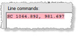
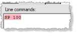
- Keyboard entry: Type SC (alpha code for Start Coordinate - SC) followed by each coordinate (separated by a comma delimiter), or type SP (alpha code for Start Point - SP) followed by a point ID. Then press the Enter key.
- Numeric keypad entry: Ensure the Numeric keypad mode check box on the Create COGO: Options tab is checked. Then press the Asterisk key ("*") once and type 00 (numeric code for Start Coordinate - SC) followed by each coordinate (separated by a comma delimiter; press "+"), or press the Asterisk key once and type 01 (numeric code for Start Point - SP) followed by a point ID. Then press the Enter key.
- Interface entry: Click the Start drop-down button and select Start Coordinate - SC or Start Point - SP. Then select or enter a coordinate or point ID and click the Enter (New Line) button.
Tip: When first using the Create COGO command, try using the interface-entry method to become familiar with creating command lines. Once you are comfortable with the workflow and the various command line options available, and if you require faster data entry, try using the keyboard or numeric keypad entry method. For a complete list of alpha (requires a full keyboard) and numeric (requires only a keypad) command codes, see COGO Linework Commands.
Note: The End commands are used to end a line at a measured point or coordinate that is fixed in the adjustment computation. These commands are typically used when performing a Grant Boundary adjustment on a parcel that has already been computed.
Although the Start Coordinate - SC or Start Point - SP command is often used to start the first new line segment, there is no previous bearing/azimuth for the coordinate or point; therefore, "relative" line creation commands cannot be used to define the first line segment (that is, commands to create line segments that are relative to the preceding line segment, such as Line by Deflection angle - LD, Line by Interior angle - LI, Line by Left 90 degree angle - LL, and Line by Right 90 degree angle - LR). Instead, you must use an "absolute" line creation command to create the first line segment (that is, a command to create a line that is not relative to the preceding line segment, such as Line by Bearing/Azimuth - LB, Arc by Bearing/Azimuth of Chord - ABC, Arc by Bearing/Azimuth of Radial - ABR, and Arc by Bearing/Azimuth of Tangent - ABT). (See COGO Linework Commands.)
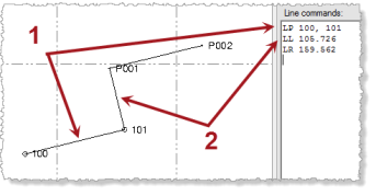
As an alternative, your input data may include two survey points that you can connect using the Line by Points - LP command (1 in the example below). With the bearing/azimuth now established for the second of the two survey points, you can use it as a starting point for the next line segment, for which you can use any of the relative line creation commands. In the example below, the Line by Left 90 degree angle - LL command was used to create a line from survey point 101 to the automatically created point P001.
By default, for "absolute" line creation commands (for example, Line by Bearing/Azimuth - LB), the coordinate for the preceding point is automatically selected for the starting reference point coordinate for the new line segment. However, you can enter or select in the Plan View a different coordinate to use for the starting reference point in the Reference point field, which will cause a new Start Coordinate - SC command to be automatically entered on a new command line prior to the new line segment command. As discussed earlier, the new line segment following the Start Coordinate - SC command must be absolute as there is no previous line segment to which it is relative.
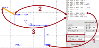
In the following example, the previous line segment ended on the coordinate for point P010 based on the Line by Azimuth- LB command (1 below). The user then selected to enter a new Line by Azimuth- LB command but changed the Reference point from the default point P010 coordinate to the point P005 coordinate, which resulted in a new Start Coordinate - SC command being automatically entered (2 below). This created a new start reference point P011 for the new line segment at the coordinate for point P005. The user then specified the Azimuth and Length to create a new line segment that starts at the new point P010 and ends at the new point P012.
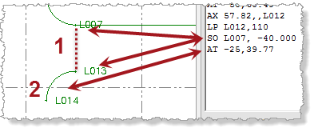
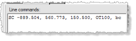
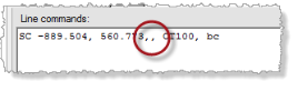
Once you have created points and lines in a COGO collection, you can also use the Start by Offset - SO command to create a new line – based on an existing point in the collection. This is useful if, for example, you need to use a road centerline as a reference from which parcel boundaries are computed. When you enter a Start by Offset - SO command, the Start point you select (the point from which the new point will be offset) must have an orientation (unlike the Start Coordinate - SC and Start Point - SP commands). This allows you to specify a Horizontal offset value for the new point at a right angle to either the right (positive value) or left (negative value) of the Start point based on its direction of travel. This means that the Start point must be in the same COGO collection and cannot be, for example, a Start by Coordinate - SC point. The Start by Offset - SO command must be followed by a line or arc command that supplies an orientation (see COGO Linework Commands). In the following example, point L013 was created as an offset start point 40 m to the left (-40.00) of point L007 based on its direction of travel (1 below). Then an arc was drawn from the new offset start point using the orientation-based Arc Tangential- AT command (2 below).
Note: Using the instructions in this step, you can create a starting reference point to "draw" a parcel that is completely enclosed (nested) within an existing parcel, allowing you to handle more complex land boundary situations. After creating the starting reference point, follow the rest of the steps in this procedure to complete the nested parcel. In the Map Check Report, nested parcel areas are treated as transparent holes in the outer parcels in which they are enclosed, and they do not contribute to the outer parcel's area.
- Keyboard entry: Type SC (alpha code for Start Coordinate - SC) followed by each coordinate (separated by a comma delimiter), or type SP (alpha code for Start Point - SP) followed by a point ID. Then press the Enter key.
- To continue defining the line using Add Line or Add Arc commands, do one of the following:
- Keyboard entry: Type the appropriate Add Line or Add Arc command code followed by the required values (separated by comma delimiters) in the sequence shown in COGO Linework Commands. Then press the Enter key.
- Numeric keypad entry: Ensure the Numeric keypad mode check box on the Create COGO: Options tab is checked. Then press the Asterisk key ("*") once and type the numeric code for the appropriate Add Line or Add Arc command code followed by the required values (separated by comma delimiters; press "+") in the sequence shown in COGO COGO Linework Commands. Then press the Enter key.
- Interface entry: Click the Add Line or Add Arc drop-down button and select the appropriate command. Then select or enter the required values. When you are done, click the Enter (New Line) button.
As you enter each command, the linework is updated in the graphic view. If a command includes an error and you start entering a new command, the command with the error is highlighted red and no line is drawn. You must edit the command to correct the error.
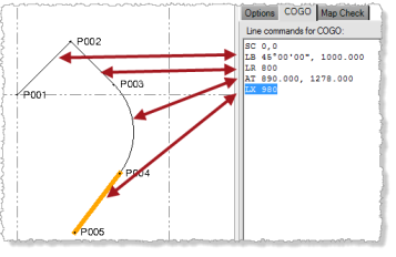
The following example shows a line created using various Add Line and Add Arc commands.
 Additional notes on entering commands...
In addition, as you enter each command, a new point or line node is added to the Project Explorer nested beneath the COGO Collections > Collection Name node. You can right-click any node and select Properties to display the Properties pane.
Note that when you enter a line, point, or arc command line (excludes start, line/arc extend, and sideshot-type commands), the command type controls stay open until you click the Leave current COGO button to enter a different type of command. This streamlines the COGO creation process when entering multiple command lines of the same type.
- To continue defining the line using Add Sideshot commands, do one of the following:
- Keyboard entry: Type RS (alpha code for Radial Sideshot - RS) or XS (alpha code for Extended Sideshot - XS). Then press the Enter key.
- Numeric keypad entry: Press the Asterisk key ("*") once and type 41 (numeric code for Radial Sideshot - RS), or type 42 (numeric code for Extended Sideshot - XS). Then press the Enter key.
- Interface entry: Click the Add Sideshot drop-down button and select Radial Sideshot - RS or Extended Sideshot - XS. Then click the Enter (New Line) button.
Use the Radial Sideshot command to define one or more radial sideshots (single-segment lines originating from the current point). Use the Extended Sideshot command to define one extended sideshot (multi-segment line originating from the current point).
If you enter a Radial Sideshot command, you must follow it with one or more Add Line or Add Arc commands as described in the previous step. Each of the single-segment lines you create will originate at the same point. For example, you could use this command to create two new sideshot lines originating from the same point on a current west-to-east line: one heads north a specified distance and one heads south a specified distance.
If you enter an Extended Sideshot command, you must follow it with one or more Add Line or Add Arc command lines as described in the previous step to create an extended multi-segment line. Each of the subsequent segments you define will originate where the previous line segment ends. For example, you could use this command to create a new sideshot line originating from a point on a current west-to-east line that heads north for 20 m and then angles to the east for an additional 10 m.
After the last Radial Sideshot or Extended Sideshot command line, enter an End Sideshot - ES command line (no values) to end the Add Sideshot command so that you can continue adding lines or arcs to the original line.
As you enter each command, the line is updated in the graphic view. If a command includes an error and you start entering a new command, the command with the error is highlighted red and no line is drawn. You must edit the command to correct the error.
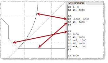
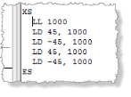
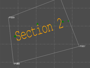
The following example shows a Radial Sideshot - RS command defining two lines originating from a point and an Extended Sideshot - XS command defining a single line with five segments originating from the same point.
 Additional notes on entering commands...Additional notes on point IDs...
Note: If you want to ensure that none of the COGO points and lines are accidentally modified after you create a COGO collection, click the Lock button preceding the Collection name drop-down list on the Options tab. Once a collection is locked, all of the editing controls on each of the three Create COGO tabs are disabled, preventing additional changes. Note, however, that you can edit any of the points or lines included in the collection using the Properties pane and/or other commands. If a change of this type is made, the Lock button background changes to red. If you do not re-click the Lock button, your changes are kept, but the COGO linework is not modified. If you re-click the Lock button, the COGO points and lines are recomputed based on the COGO commands, undoing any property changes that were made.
If you intend to create parcels from the COGO linework you have created, proceed with "Step 3. Create parcels and compute parcel closure (Optional)" below.
Step 2b. Create COGO linework automatically from existing project linework
If your project already contains boundary CAD linework, use this procedure to automatically create a COGO collection from your selection.
Note: If you are manually creating COGO linework in your project based on paper-based data, such as a plot map, see "Step 2 a. Create COGO linework manually from paper-based data" above.
- Select the COGO tab.
- In the Plan View, select the boundary linework in your project you want to use to create COGO linework.
Boundary linework must be closed to be included in the COGO collection.
- Click the Add from Selected Linework button.
The Line commands list is automatically populated with COGO linework commands and the resulting COGO linework is displayed in the Plan View.
If necessary, you can make any corrections by manually editing any of the linework commands manually as described in "Step 2 a. Create COGO linework manually from paper-based data" above.
If you intend to create parcels from the COGO linework you have created, proceed with "Step 3. Create parcels and compute parcel closure (Optional)" below.
Step 3. Create parcels and compute parcel closure (Optional)
- Select the Map Check tab.
This tab allows you to create parcels from the linework you have entered and create a Map Check Report that shows the accuracy of the data.
- In the Parcel layer drop-down list, select the layer on which to display the parcels.
To avoid confusion, it is recommended that you select one layer to display the COGO linework and a different layer to display the resulting parcels. For example, a COGO line that is the shared boundary between two parcels is drawn in exactly the same location as the two parcel boundaries, making it difficult to tell them apart if they are displayed on the same layer.
- In the Maximum misclosure field, enter or select a parcel closure tolerance distance that, if exceeded, will prevent a parcel from being created.
Select a tolerance distance that provides the level of precision you require.
Note: You may need to experiment with different misclosure distances to ensure parcels are being created correctly per your expectations. Try to avoid values that are larger than you need.
In addition, you can use the Project Settings dialog (Computations > COGO) to change the maximum precision ratio for parcels. Precision is defined by the ratio of the parcel's perimeter distance divided by the sum of the misclosures. If this ratio is exceeded, the parcel will still be created (if it does not exceed the value specified in the Maximum misclosure field), but an out-of-tolerance flag will display with it.
- Optionally, check the Skip parcels with two or more misclosures check box if you want to prevent a parcel from being created if it includes multiple misclosures.
- Optionally, uncheck the Use only node-to-node misclosures check box to ease the parcel-creation rules and allow temporary nodes to be created at line intersections to calculate misclosure and create parcels, instead of requiring that misclosure be calculated based on existing vertex nodes.
By default, this check box is checked and this option is recommended to ensure the highest accuracy in misclosure computations. Although unchecking this option enables the software to create parcels despite large misclosures, the software is forced to use calculations that might not meet your quality requirements. As an alternative, it is strongly recommended that you create new nodes as necessary using a CAD command such as Break Line.
For more information on unchecking the Use only node-to-node misclosures check box, click here.
- Optionally, click in the Include field and then select in the Plan View any additional linework you want to include in the parcel computation. Click Options for additional selection options.
If you make no selection, only the current COGO collection will be included in the computation.
This option is helpful if your parcels depend on linework created outside the current COGO collection, including linework created with other COGO collections in the project.
Notes:
- Be careful when selecting objects to included in the COGO collection. You might accidentally select objects (for example feature lines) that will cause unexpected results.
- If you want to include linework from other COGO collections in the project, be sure to select it in the Plan View. Anytime you select a different COGO collection in the Project Explorer, it becomes the active COGO collection in the Create COGO command pane. - Do either of the following:
- Click the Create Parcels button if you want to delete any existing parcels and create all new parcels in the collection.
If parcels already exist in the collection, the old parcels are deleted before the new parcels are created. However, a comparison of the old and new parcels is made during the creation process and if any new parcel is found to match an old parcel, the properties of the old parcel, including the parcel name, are copied to the new matching parcel before the old parcel is deleted.
- Click the Add Parcels button if you do not want to delete any existing parcels but instead create new parcels to add to the collection. This supports a workflow in which, when working with large projects, you can create COGO linework and parcels in batches, while maintaining the integrity of your parcel naming scheme.
TBC attempts to identify the enclosed areas with a misclosure less than the specified tolerance and creates a parcel for each of those areas. The individual parcels are highlighted in the graphic views and each includes a translucent background and an auto-generated numeric parcel name.
The results of the parcel creation process are displayed in a list beneath the Create Parcels button. Reasons for failing to create a parcel include having too much misclosure, having too many misclosures, or being poorly formed. If parcels failed to be created for any of the reasons mentioned, or no reason is specified, review your linework to determine where the problem(s) might exist. To help you locate the failed parcels, click the Create Parcels button to select (highlight) it, then press Ctrl + Enter. This will cause unnamed "pseudo parcels" to be created where real parcels failed to be created, allowing you to more closely examine the linework to identify problems. Then, as necessary, do either or both of the following:
- Modify/correct the linework as described above.
- Experiment with different Maximum misclosure distances.
Each parcel is separate and wholly independent of other parcels. For example, you could delete a parcel without affecting any of the other parcels adjacent to it.
Note: If you want to change any of the COGO linework for a newly created parcel, you should first delete the parcel and then recreate it after your linework changes are complete. To delete all of the newly created parcels, you can click the Remove Parcels button.
The Label Parcels button allows you to quickly and easily apply line labels to the newly created parcels using the Label Lines command. In this case, the parcel drawing in the Map Check Report (described later in this procedure) will include the newly created labels, thus providing all of the information necessary to reproduce the parcel in future surveys.
Note: Any labeling that has already been assigned to CAD linework used to create the parcels does not display in the Map Check Report as it may not accurately represent each parcel's boundary. Only labels that are assigned as described in the next step are displayed in the Map Check Report.
- Click the Create Parcels button if you want to delete any existing parcels and create all new parcels in the collection.
- To add labels to the parcels, click the Label Parcels button and do the following:
- In the Label Lines command pane, select the appropriate Line label style, Layer, and Maximum line length.
If you want the labels to display in the Map Check Report but not in the Plan View (for example, the linework already includes labels that you want to display in the Plan View, and you do not want the new labels to overlay them), select to display the labels on a layer that you can hide using the View Filter Manager.
See Create Line Labels for additional instructions on assigning line labels.
Note that the parcel linework is already selected in the Multi-select lines to label field.
- Click the Add button.
The labels are displayed in the Plan View.
- Click the Close button.
- In the Label Lines command pane, select the appropriate Line label style, Layer, and Maximum line length.
- On the Map Check tab, click the Map Check Report button to view a report on the newly created parcels.
The report includes a section for each parcel that includes summary information (traverse length, total misclosure, precision ratio, scale factor, area, and source), a misclosure table, a linework table, and a drawing of the parcel.
If you used the Label Parcels button to add labels to the parcels, the Map Check Report includes the labels in each of the parcel drawings. In addition, total misclosure and precision ratio values based on the rounded label values (in addition to the virtually unrounded total misclosure and precision ratio values included in the summary section for the parcel). These values can be modified by using line labels of varying decimal precision, enabling you to ensure adequate precision for the parcel labeling.
Note: By default, ground precisions, if they are included, are not displayed in the Map Check Report. To display ground precisions in the report, you must edit the report's settings using the Report Options command pane.
- If you want to enter a description/location for a parcel and/or change its auto-generated numeric parcel name, do the following:
- In the Parcel description/location field, enter a description/location.
The description displays in parcel's Properties pane.
- In the Parcel name field, enter a new name.
The name displays in the graphic views and the parcel's Properties pane.
- Click in the Click parcels in order field and select the parcel to which you want to apply the new name.
- Repeat as necessary to rename any or all of the newly created parcels.
Note that if you do not change the Parcel name field, the name for each subsequent parcel will be the same but an auto-incremented numeric suffix will be added.
- In the Parcel description/location field, enter a description/location.
- When you are done, click Close.
To make view or make changes to the properties for any parcel, select it in a graphic view or in the Project Explorer, right-click, and select Properties.
Because each parcel name is saved as a CAD multiline text object, when the Create COGO command pane is closed, you can select the text to display icons in the Plan View that allow you to move, resize, and/or rotate the text to fit appropriately within the parcel boundaries. You can also select the text, right-click, and select Properties to display the Properties pane where you can change the text and various text properties.
Note: You can generate a Point Comparison Report for a selection of point-related objects that includes all of the point pairs that are within a user-specified proximity and flags those that exceed a user-specified horizontal and/or vertical tolerance value. This is useful for comparing measured and office entered data. For example, you can compare COGO point data entered from survey plans and plats to survey data collected on site to verify the accuracy.
Edit an existing COGO collection:
Do either of the following:
- To make edits to the properties for a COGO collection and/or modify COGO points or lines, right-click the COGO collection in the Project Explorer and select Edit to display the collection in the Create COGO command pane.Then make changes as described earlier in this topic.
- To make edits to any of the individual linestrings in the COGO collection, select the segment in a graphic view (or select the entire linestring in the Project Explorer), right-click, and select Edit to display the COGO tab in the Create COGO command pane. Then make edits as described in "Step 2 a. Create COGO linework manually from paper-based data" above. (For instructions on editing line commands to perform a Grant Boundary Adjustment, see Perform a Grant Boundary Adjustment on a Computed Parcel.
Notes:
- If you make changes in the Horizontal distances group box and/or the Curved distances group box on the Options tab, existing COGO linework will change accordingly, possibly causing unexpected results.
- If you change the coordinates for a COGO-generated point using the Properties pane, the COGO linework associated with the point will not change.
- Additional notes on entering commands...
- Additional notes on point IDs...
