Create Legal Descriptions
Use the Legal Description Writer command to automatically generate a collection of textual legal descriptions for cadastral survey projects that include parcels (created with the Create COGO command) and/or polygons, or closed linework (see following note). The command is capable of describing complex geometry for multiple parcels and polygons using multiplestarting points and paths. A fully customizable template specifies the distance, direction, angular, and area formats to be used in the legal descriptions, along with the specific phrasing to be used to describe the location of each parcel or polygon. This allows you to provide any customization required to create deed descriptions specifically for local and national land registry offices. Deliverables are provided in TXT and RTF file formats. The Legal Description Writer provides a handy and powerful integrated workflow for creating legal descriptions right in TBC without the need for a third-party tool.
Note: To simplify the wording in the following instructions, closed linework for which a legal description is generated is referred to as a "polygon," even though it is not really a polygon CAD object in the project.
Prerequisites:
See the Subscription Plans page. For a license matrix by command, see the License page in the TBC Community. Also see View and manage licensed features.
To create legal descriptions:
- Select Legal Description Writer in Survey > COGOto display the Legal Description Writer command pane.
Next you will select the template to use to create the legal descriptions. The template, which is fully editable, specifies the distance, direction, angular, and area formats to be used in the legal descriptions, along with the specific phrasing to be used to describe the location of each parcel/polygon. When editing the template, you will be able to preview its output with your project data.
- In the Template file drop-down list, select the template you want to use for the creation of the legal descriptions. Or, click the Browse button to select a template not included in the drop-down list (for example, a template created by a different user that is stored on a shared network drive).
You can select the read-only <Default> template, which is based on the DefaultLegalDescriptionTemplate.xml file installed with TBC, or you can select a previously created template. If you select the read-only <Default> template, you will be prompted to save it with a new name if you make changes to it in the Description Template Editor.
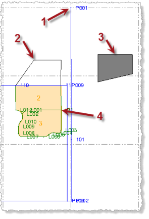
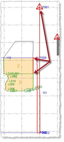
The following project example will be used to illustrate the steps in this procedure. It includes a control point that can be used as a Point of Commencement starting point (1 below), a set of closed line segments (2), a polygon (3), and two parcels (4).
- Click in the Select starting points field, and then select one or more starting points for the legal descriptions.
Each starting point you select can be either a Point of Commencement (a control point that is not on any of the parcel/polygon boundaries' vertices but instead is located away from the parcels/polygons, as in the case of a survey marker in the middle of an intersection) or a Point of Beginning (a vertex point on a parcel/polygon boundary). A Point of Commencement start point requires that you select line segments to connect it to one or more parcels/polygons as described in the next step.
When a Point of Commencement start point is used, the legal description starts with a Point of Commencement phrase, followed later in the description by a Point of Beginning phrase. When a Point of Beginning start point is used, the legal description starts with a Point of Beginning phrase.
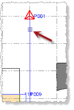
- To select a Point of Commencement starting point for one or more parcels/polygons:
- Click near the end of any line segment whose end point is a Point of Commencement control point.
- Repeat to select additional Point of Commencement starting points as necessary.
For example, you might be creating legal descriptions for multiple parcels/polygons that lie between two control points. If you select both control points as Point of Commencement starting points, the software will automatically use the starting point that is closest to each parcel to create its legal description. In this case, half of the parcels might use one Point of Commencement starting point while the other half use the other Point of Commencement starting point. This ensures the legal descriptions are as concise and error-free as possible.
Proceed to the next step to select the line segments that connect the Point of Commencement starting point to one or more parcels.
- Click near the end of any line segment whose end point is a Point of Commencement control point.
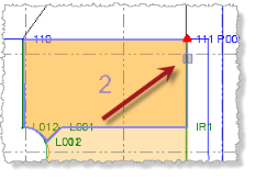
- To select a Point of Beginning starting point for a parcel, click near the end of any parcel boundary line segment to select the associated vertex point as the Point of Beginning starting point.
Repeat to select Point of Beginning starting points for additional parcels as necessary.
- To select a Point of Beginning starting point for a polygon, click near the end of any polygon boundary line segment to select the associated vertex point as the Point of Beginning starting point.
Repeat to select Point of Beginning starting points for additional polygons as necessary.
Precise clicking is not required because the software will find the closest end point on the line segment and specify that as the starting point.
If you do not select either Point of Commencement starting points or Point of Beginning starting points, the software will automatically select a Point of Beginning starting point for each selected parcel/polygon.
Note: To de-select all of your selections, select the value displayed in the Select starting points field and press the Delete key, or right-click and select Clear.
- To select a Point of Commencement starting point for one or more parcels/polygons:
- If you selected a Point of Commencement for a starting point, click in the Select path segments field, and then select the line segments that connect the starting point to a Point of Beginning vertex point on each of the parcels or polygons to be included in the legal description.
Note: If you selected a Point of Beginning for the starting point, there is no need to select line segments in the Select path segments field.
The sequence in which you select line segments is inconsequential as the software will automatically determine the correct sequence for the descriptions.
As an alternative to selecting line segments individually, you can right-click and select Select All to select all of the segments displayed in the Plan View, or you can select all of the segments that might possibly be used by drawing a selection box around them in the Plan View. (To enable the selection cursor, you must first click somewhere other than in the one of the three selection fields in the Legal Description Writer so they no longer have focus.) From the selected line segments, the software will determine the best line segments to use for the path from the Point of Commencement to each parcel you select to include in the legal descriptions (see next step).
If you are selecting line segments individually, it is important that the line-segment path you create connects to a Point of Beginning vertex point for each of the parcels/polygons to be included in the descriptions. If the path does not connect to a parcel/polygon you select to include in the legal descriptions (see next step), the software automatically specifies a Point of Beginning vertex point for the selected parcel/polygon, ignoring the Point of Commencement starting point.
In the following example, six segments were selected to create an unbroken path from the Point of Commencement starting point to a vertex on each of the two parcels (2 and 3) to be included in the legal description.
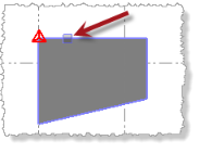
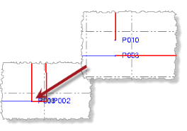
You may need to zoom in on the Plan View to determine if there are any small gaps in the line-segment path. If there is a gap and it is less than the Gap Tolerance specified on the Edit >Description Template tab in the Description Template Editor, the gap is ignored and the path will function correctly to create legal descriptions for the linked parcels/polygons. If the is gap greater than the specified tolerance, the broken path will result in no legal descriptions being created. Following is an example of a gap that was too small to see without zooming in very close. See step 6 for additional information on identifying line segment gaps.
If you want to create a legal description for a "polygon" formed by closed line segments (as opposed to a parcel or polygon CAD object), you must do the following:
- Select all of the line segments that form the polygon boundary as path segments from the Point of Commencement starting point.
- Ensure that no parcels/polygons are selected in the Select parcels field (see next step).
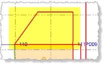
If all of the line segments are not selected, or if one or more parcels/polygons are selected in the Select parcels field, no legal description will be created for the closed line segment. In the following example, all of the line segments representing the closed linework were selected so a legal description could be created for the linework. If no parcels/polygons are selected in the Select parcels field, a legal description will be created for the closed line segments.
To de-select all of your selections, select the value displayed in the Select path segments field and press the Delete key, or right-click and select Clear.
Note: When you create a legal description for a parcel, the parcel's name and description (see Create COGO Collections and Compute Parcels) are automatically included in the legal description. When you create a legal description for a polygon or closed-line segments, the legal description does not automatically include this information since it is not included in the properties for these types of objects. In this case, you must enter it manually in Preview mode in the Description Template Editor. For this reason, it is recommended that you convert polygons and closed-line segments to parcels before creating legal descriptions.
- Click in the Select parcels field, and then select each of the the parcels/polygons you want to include in the description.
If you are creating legal descriptions for closed linework, do not select anything in this field.
As an alternative to selecting parcels individually, you can right-click and select Select All to select all of the parcels displayed in the Plan View, or you can select the parcels by drawing a selection box around them in the Plan View. (To enable the selection cursor, you must first click somewhere other than in the one of the three selection fields in the Legal Description Writer so they no longer have focus.) To de-select all of your selections, select the value displayed in the Select parcels field and press the Delete key, or right-click and select Clear.
- Optionally, uncheck the Use only node-to-node misclosures check box to ease the description-writer rules and allow temporary nodes to be created at line intersections to create the shortest path to a parcel when a gap in the linework exists, instead of requiring the path to use existing vertex nodes.
By default, this check box is checked and this option is recommended to ensure the highest accuracy in the descriptions. Although unchecking this option enables the software to create paths despite large gaps, the software is forced to use calculations that might not meet your quality requirements. As an alternative, it is strongly recommended that you create new nodes as necessary using a CAD command such as Break Line.
For more information on unchecking the Use only node-to-node misclosures check box, click here.
- If you selected all or a subset of all of the line segments (as noted in step 4), allowing the software to calculate the shortest path from a Point of Commencement to each parcel, click and hold the Show Calculated Path button to display the calculated paths.
Although you can view the calculated paths for multiple parcels selected in the Select parcels field, it is recommended that you view the path for one selected parcel at a time to avoid confusion as to which path belongs to which parcel.
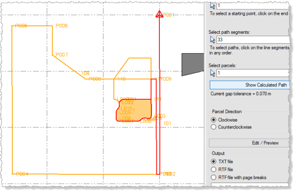
If you see unexpected results (for example, a longer or more circuitous path than you were expecting, or no path at all), it may be due to a gap between line segments that is not obviously visible at your current view zoom level, preventing what otherwise might be a shorter path from being calculated (as described in step 4).The currently selected gap tolerance is displayed beneath the button. Gaps that are greater than this value will cause a path to not be calculated using those line segments. In this case, an appropriate message is displayed, and the location of the segment misclosure is marked with a red circle and a gap distance value. Optionally, you can increase the gap tolerance to enable a path to be calculated. To do so, press the Edit / Preview button to display the Description Template Editor dialog. Then select the Description Template node on the Edit tab.
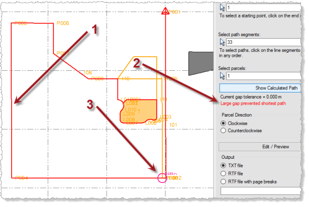
In the following example, the calculated path to the selected parcel is unnecessarily long (1 below) due to the fact that a misclosure, which cannot be seen without zooming in much closer, is preventing a shorter path from being calculated. An appropriate message is displayed (2) and the location of the misclosure is identified (3).
By zooming in on the misclosure, you can see the size of the gap that is preventing a shorter, more direct path from being calculated.
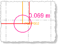
After increasing the gap tolerance to .070 on the Edit > Description Template tab in the Description Template Editor dialog, a shorter path is calculated.
Note: Although the Gap Tolerance feature can be helpful in dealing with very small measuring errors that are difficult to locate, entering too large of a gap value can result in incorrect descriptions without you knowing it. It is highly recommended that you inspect all of your linework for gaps and overlaps prior to creating a legal description.
- Select the appropriate Parcel Direction:
- Clockwise - The legal description follows a clockwise path around the parcel or polygon.
- Counterclockwise - The legal description follows a counterclockwise path around the parcel or polgon.
- Click the Edit / Preview button to display the Description Template dialog, which allows you preview the legal descriptions based on your settings and selections in the Legal Description command pane and, if necessary, make manual edits to the descriptions or modify the selected Legal Description template. For complete instructions see Preview a Legal Description and Edit Templates.
- When you are done previewing and, if necessary, editing the legal descriptions using the Description Template Editor, select the appropriate Output option:
- TXT file - Create a text (.txt) file that can be opened with any text editor. Five blank lines are inserted before each description.
- RTF file - Create a Rich Text Format (.rtf) file that can be opened with MS Word and other RTF editors. Five blank lines are inserted before each description.
- RTF file with page breaks - Create a Rich Text Format (.rtf) file that can be opened with MS Word and other RTF editors. A page break is inserted before each description.
- Click the Output Browse button to name the output file and specify a location to store it.
- Click the Apply button.
- If you selected the RTF format, In the Convert File dialog, click OK.
The new document file opens in a text editor window. If necessary, you can make additional edits to the content or formatting of the document.
