Create Line Labels
Create single- or multi-line labels for line segments using predefined line label styles. Picking a single segment on a line labels that segment. Selecting multiple lines at once labels every segment of each line.
After it is created, a line label is dependent upon the line segment it is labeling; if the segment is changed or deleted, the label will be changed or deleted accordingly.
Note: To ensure that the size of dimensions or labels is correct when viewed in the Plan View, verify that the plot scale for the project is set correctly in Project Settings > View > Plan View. The plot scale is the factor used to convert from ground units to sheet units (ground units / plot scale = sheet units). For example, if the default plot scale of 600 is used, an object with a length of 600 m in the Plan View will plot with a length of 1 m on paper. In survey feet, the default plot scale of 50 will plot as 1 foot on paper.
Prerequisites:
- Licensed module. See the Subscription Plans page. For a license matrix by command, see the License page in the TBC Community. Also see View and manage licensed features.
- One or more lines
To create line labels:
- Select Label Lines in Drafting > Labels to display the Label Lines command pane.
Before you select line segments to label, you will set a few labeling properties.
- In the Line label style drop-down list, select the style you want to apply to the new line label, or select <<New Style>> to create a new style using the Label Style Manager.
- Optionally, select a different Layer for the new labels. If necessary, select <<New Layer>> to create a new layer for the labels.
- In the Minimum line length field, specify the minimum length of a line segment to which the label will be applied.
Selected line segments that are shorter than this length will not be labeled unless you select to include them in a label table as described in the next step.
- If you want to include selected line segments that are less than the minimum length in a label table, do the following:
- Select the Add small segment to table check box.
- In the drop-down list, select the label table to which you want to add the segments, or select <<New ...>> to create a new label table.
- To specify that the line direction (the direction in which the line was "drawn"; for example, from left to right) determine the "top" and "bottom" of the line for label placement, check the Keep line direction placement check box.
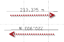
When you create a line label style in the Label Style Manager dialog, you specify whether label lines should be located above or below the line segment. For example, you might specify that the segment distance be displayed above the line segment. In this case, if the Keep line direction placement check box is unchecked, the distance will be displayed "above" the line in the Plan View regardless of the line's direction. (The arrows in the following images show the line directions.)
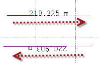
If the Keep line direction placement check box is checked, the distance will be displayed "above" the line in the Plan View based on the line's direction.
You now have the choice of labeling line segments individually or labeling multiple line segments simultaneously as described in the following steps.
- To create a label for one or more individual line segments, do the following:
- Click in the Select segment to label field.
- Select the line segment in the Plan View.
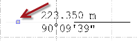
Where you click on the line segment when making your selection determines the direction of the label text. For example, if you click on the left half of a horizontal line segment, the text runs from left to right. If you click on the right half of the segment, the text runs from right to left, causing the text to display upside down. To change the text direction, click the line segment a second time to remove the label, then click the line segment a third time on the other half of the segment, or in the Properties pane set Auto flip to Yes.
Click on left half of segment:
Click on right half of segment:
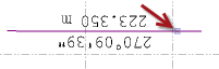
Note in the examples above that the azimuth/bearing changes depending on which half of the segment you select.
- Optionally, click additional segments to apply labels to those segments as well.
- To create labels for multiple line segments simultaneously, do the following:
- Click in the Multi-select lines to label field.
- Select the line segments you want to label.
For example, select a multi-segment polyline, select multiple line segments using Ctrl + click or by drawing a box, or select the Options button to make your selections.
- Click the Add button to create the labels for the selected line segments.
The labels display with each of the selected segments or, if applicable, in a label table. The direction of the label text is determined by the direction in which the line segment was "drawn."
To remove all of the labels, click the Remove button.
- When you are done, click Close.
This command is available in the command pane and by right-clicking in the graphic view.
Note: You can edit the appearance of a selected label, including the position of the leader line's connection to it (top, middle, or bottom), in the Properties pane.
