Define Topsoil Stripping Areas
Use the Define Topsoil Stripping Areas command to identify areas where topsoil should be stripped (removed) from your Original ground (OG)surface. Select one or more areas and specify a stripping depth. Each area must be bordered by a single closed line or boundary. These lines can be selected from existing lines or digitized as polylines within this command. In addition to the Original surface, a new surface, named OG with topsoil stripped is created to show the stripped areas.
Note: For more information on the types of surfaces that are automatically created by certain takeoff commands, see Understanding Takeoff Surfaces. For information on strategies for defining topsoil areas, see the document entitled Defining Topsoil Handling Areas in the Community.
Note: When computing a topsoil stripping surface, non-breakline triangle edges that cross the offset line are included in the formation of the new surface, unless the Volume computation project setting is set to Track Finish Breaklines (in Project Settings > Computations > Surface> General). The additional points that are created improve the depth consistency of the new surface at the expense of slowing the calculations.
Digitizing stripping areas
This command is optimized for digitizer input; you can enter a constant stripping thickness for each polyline from the digitizer puck without returning to the on-screen command pane. To quickly and simply digitize multiple polylines, use the Workflow for digitizing multiple polylines at the end of the Create a Polyline help topic. In that workflow, substitute "thickness" for "elevation".
Prerequisites:
- License; See the Subscription Plans page. For a license matrix by command, see the License page in the TBC Community. Also see View and manage licensed features.
- Native topsoil material defined in the Material and Site Improvement Manager
To define topsoil stripping areas:
- Select Define Topsoil Stripping Areas in Takeoff > Takeoff.
The Define Topsoil Stripping Areas command pane displays.
- If needed, click the Project Settings icon at the top of the pane to check that the Topsoil offset method to use is set correctly. Close the Project Settings when you are done.
Note: Selecting Perpendicular as the offset method will result in greater topsoil volumes, since it applies the designated thickness perpendicular to the slope of the surface. Selecting Vertical lowers the Original ground
surface by the specified thickness. - If you have defined strata based on boring logs, and the upper-most stratum is a topsoil material, it will use that stratum to determine the material to be stripped. The material of the topsoil stratum will appear under the label Presumed topsoil stratum. In this case, you can elect to specify a constant thickness to which the topsoil will be stripped within a designated stripping area using the Thickness box, or you may elect to check the Strip uppermost stratum box, in which case the topsoil stripping volume will be computed based on the variable thickness of that uppermost stratum. Skip to step 13.
Note: If the top-most stratum is not topsoil (no topsoil is available for stripping) the command is disabled. Unless your project includes landscaping topsoil site improvements in which topsoil replacement has been designated, or you have designated one or more of those site regions as one using excess topsoil earth fill, the Topsoil Handling section of the Takeoff Report will also be disabled.
If you have not defined any strata on the site, specify the depth from the top of ground to which the soil should be stripped in the Thickness box.
This defines the amount of material to be removed from the top of the Original ground surface to form the OG with topsoil stripped (& subgrades demolished) surface. The volume of the topsoil stripped from the surface can later be reported in the Takeoff Report. There, the Topsoil Handling (stripping, replacement and excess topsoil earth fill) operations are reported separately from the cut/fill volumes associated with a Mass Earthwork Analysis.
- In the Native topsoil material list, select the topsoil material you created to represent the top-level material on the site that needs to be stripped, or select <New> to create one. If you are not ready to create a topsoil material, select <Undefined>. This enables you to define stripping areas, but the material will not have shrinkage, bulkage, and compaction values.
- To digitize new lines for a topsoil boundary, scroll down to the Digitize group. Otherwise, skip to step 13.
Note: If your digitizer is not connected, the Digitize group is collapsed.
- In the Name box, type an identifier for the polyline as you want it to appear in the Selection Explorer and graphic views. You can also use the name to select the polyline in the Advanced Select command.
- Select the layer on which you want the polyline to reside in the Layer list, or select <<New Layer>> to create a new layer for the polyline.
- Select a Filter type below the Next points box:
- Circle - In the Radius box, specify the minimum radial distance from the last point that the next point can be added.
- Tube - In the Length and Width boxes, specify the dimensions of a rectangle to be positioned in line with the last two created points with its midpoint at the position of the last created point. After positioning that rectangle, any digitized data point that lies within it is ignored. To be accepted, a point must be found to lie beyond the end of the rectangle’s length, or outside of either edge defined by its width, or both. Polylines are drawn in 2D, so this is not a 3D filter.
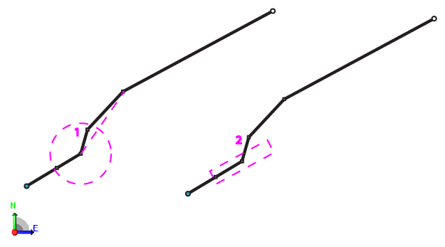
Figure: Line digitizing filters
1. Circle filter - Node 1 within the filter will be removed, resulting in the dashed path
2. Tube filter - Node 2 outside of the filter will not be removed, retaining the original path of the line
Tip: Start with a filter radius/length of 3 feet/1 meter. Then adjust the tolerance up or down depending on your needs.
Tip: If you zoom in close enough, the above noted circle or rectangle representing the filter will be displayed. This will help you to easily understand how it works.
Note: If you start a new polyline, the same filter settings are used until you change them. - Click in the Next points box.
- Pick individual points on your paper plans with the digitizer puck to create a simple polyline, or pick the first point of the polyline, hold down the digitizer button, and move along the path of the topsoil boundary. At the end of the polyline, release the button. Points are created based on the tolerance set in Filter Settings.
Note: The polyline is closed by default, so pick points in an order that will not create overlapping lines.
Note: While in the Next points box, you can press [Backspace] to undo the last segment that was created. - Press [Enter] or click New to start a new polyline. The polyline that you just created is added to the current topsoil area. The name of the new polyline is automatically incremented and the focus returns to the Next Points box.
Note: While in the Next points box, you can also specify a constant thickness for the stripping within the resulting boundary line.
- To add existing lines to the set of topsoil stripping boundaries, click in the Closed lines box.
- In a graphic view, pick one or more lines that form closed boundaries around each topsoil stripping area you want to add, or click Options and choose a selection method in the context menu.
Note: If one of the lines you selected is not a closed line, you will be notified. You can use the Join Lines command to form a single closed line from multiple lines, or you can use the Track Region Outline
command to form a closed line within a region formed by multiple intersecting lines.
Note: If you need to exclude an interior region from a topsoil stripping area (create a hole in the larger area), add the line bounding the interior region/hole as a stripping boundary with a thickness of 0.00. - Click Add/Update to add the selected area to the set of areas for topsoil stripping.
- In a graphic view, pick any previously added stripping boundaries that you want to remove from the set, and click Remove.
Note: You can use the Selection Explorer to confirm which lines have been defined as topsoil stripping areas. Click Topsoil stripping in the Selection sets list at the top of the pane.
- Click Close when you are finished.
- Select Build Takeoff Surfaces in Takeoff > Takeoff to strip the specified thickness from your takeoff surfaces.
- To review the resulting surface (OG with topsoil stripped), use the Surface Slicer View.
