Create, Edit, and Adjust a Traverse
A surveyed traverse may or may not have been adjusted in the field. If it was not adjusted in the field, you can use the Adjust Traverse command to select the stations for the traverse, specify adjustment properties, and compute the adjustment. If it was adjusted in the field, you can use the Adjust Traverse command to, as necessary, make edits to the traverse stations list, edit adjustment properties, and re-adjust the traverse.
This topic includes the following sections:
- "To create and adjust a traverse" - Use this procedure when raw (unadjusted) traverse data has been imported into the project and you need to select the traverse stations, specify settings, and compute the adjustment.
- "To edit and re-adjust an existing traverse" - Use this procedure when a traverse has already been adjusted and you want to make changes to the station list and/or adjustment settings and re-compute the adjustment.
- "To manually adjust a traverse" - Use this procedure when a traverse-adjusted coordinate in an "Adjust manually" mode traverse has an out-of-tolerance flag attached to it.
To create and adjust a traverse:
Use this procedure when raw (unadjusted) traverse data has been imported into the project and you need to select the stations to include in the traverse, specify settings for the traverse, and compute the adjustment.
- Before creating and adjusting a traverse, verify the traverse project settings in Project Settings > Computations > Traverse.
- Select Adjust Traverse in Survey > Optical to display the Adjust Traverse command pane.
- In the Traverse name field, enter a name for the new traverse and click the Create button.
If any traverses already exist in the project, they are displayed in a drop -down list for you to select to edit. In this case, select <Create new traverse> in the list.
An asterisk is displayed with the new traverse name until you click Apply to actually create the traverse.
All stations that you can select as a start station for the traverse are displayed in the Stations row drop-down list.
- Use the Stations row drop-down list to select the start station for the traverse. Then click the Add button
 .
.You can also select the station in the Project Explorer (select the station in the Imported Files folder) or in the Plan View (select an observation from the station).
The selected station is displayed at the top of the list and a new row drop-down is displayed containing all of the potential "next" intermediate stations in the traverse.
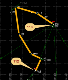
In the following example, the user wants to create a traverse between stations 112 and 118.
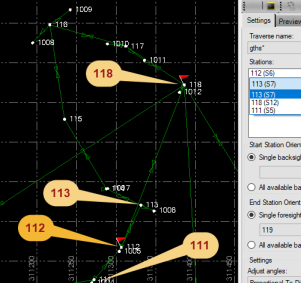
In this next screen shot, 112 has been selected as the start station for the traverse, so stations 111, 113, and 118 are the only viable "next" (intermediate) stations.
- Using the same procedure, select all subsequent intermediate stations and the end station for the traverse.
The observation between each of the stations added to the traverse is colored red in the Plan View to make the traverse easily identifiable.
As you select each intermediate station, the row drop-down list is automatically filtered to display only the viable "next" station(s).
Anytime there is only one viable "next" station, it is automatically selected. If the automatically selected station itself has only one viable next station, it is automatically selected as well, and so on as necessary until the end station is reached or you need to intervene to select between multiple options. If the automatic selection process proceeds to a station beyond which you want to end the traverse, simply select the Delete icon for the extra stations to "back up" the traverse.
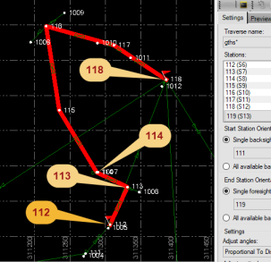
In the following example, stations 113 and 114 were selected as the next two intermediate stations following the start station 112. When the user added station 114, subsequent intermediate stations 115, 116, 117 and 118 were selected automatically as there were no other options available; that is, there was no need for the user to make any choices until station 118 was automatically selected, completing the traverse.
Notes: A station cannot be specified as an intermediate station in more than one enabled traverse. If you attempt to create a traverse containing one or more intermediate stations that are used in a different traverse, you will be prompted to disable one of the traverses before continuing.
After you have selected the end station, you are ready to specify how orientation is to be computed for the start station and end station.
- In the Start Station Orientation group box, do either of the following:
- Select the Single backsight option and select a single backsight point to use to compute the start station orientation. The Backsight drop-down list includes all of the viable backsight points.
- Select the All available backsights option to specify that the orientation for the start station be computed automatically based on all of the available backsight points.
Note: The Start station: Azimuth field is editable only if an azimuth was entered in the field and imported into the project. When creating a new traverse in the office, the Azimuth field is not editable.
- In the End Station Orientation group box, do one of the following:
- Select the Single foresight option and select a single foresight point to use to compute the end station orientation. The Foresight drop-down list includes all of the viable foresight ponts.
- Select the All available backsights option to specify that the orientation for the start station be computed automatically based on all of the available backsight points.
Note: The Start station: Azimuth field and End station: Azimuth field are editable only if an azimuth was entered in the field and imported into the project. When creating a new traverse in the office, the Azimuth field is not editable.
- In the Settings group box, optionally make adjustment changes as necessary.
- Adjust angles
- Proportional to Distance - Adjustments are weighted more heavily for angles with longer traverse lines than angles with shorter traverse lines.
- Equal Proportions - Angle adjustments are weighted equally regardless of the length of the traverse lines.
- None -No angle adjustment is performed.
- Adjust elevation
- Proportional to Distance - Adjustments are weighted more heavily for elevations with shorter traverse lines than elevations with longer traverse lines.
- Equal Proportions - Elevation adjustments are weighted equally regardless of the length of the traverse lines.
- None - No elevation adjustment is performed.
- Adjust horizontal
- Transit - In this adjustment method, it is assumed that directions are measured with higher precision than distances.
- Compass/Bowditch - In this adjustment method, it is assumed that distances and directions are measured with consistent precision.
- None - No horizontal adjustment is performed.
- Mode
- Adjust automatically - In this mode, whenever the project is computed, the traverse adjustment is also computed and any changed traverse-adjusted coordinates are saved. In this manner, the coordinates dynamically respond to changes in the input data.
- Adjust manually- In this mode, whenever the project is computed, the traverse adjustment is also computed but no changes to the current traverse-adjusted coordinates are made. However, if a re-computed coordinate is out of tolerance with the current coordinate based on settings in Project Settings > Computations > Traverse, a flag is placed on the station alerting you that you need to manually recompute the traverse using the Adjust Traverse command pane.
- Status - The options are Enabled and Disabled. Disabling a traverse retains the settings and station list in the project, but for all other considerations it behaves as though it had been deleted. This allows you to, for example, define two traverses that could not otherwise coexist (you can define two traverses that share the same intermediate station) for planning and testing purposes.
- Adjust angles
- Select the Preview Results tab to see the results of a traverse adjustment based on the information you entered on the Settings tab.
Data displayed on the Preview Results tab does not affect the project until you click the Apply button.
- Based on the results in the Preview Results tab, optionally make additional changes on the Settings tab and again view the results on the Preview Results tab. Repeat as necessary until the desired results are obtained.
Optionally, to adjust the start azimuth in a traverse, in Project Explorer expand the start point of the traverse. Double-click the Azimuth property to open the Properties pane. Under Point information, use the Quality drop-down menu to select the azimuth quality.
- Control Quality - The azimuth will not be corrected. Set the azimuth deviation tolerance in Computation Settings.
- Survey Quality - The azimuth will not be corrected.
- Mapping Quality - The azimuth will not be corrected.
- Unknown Quality - The azimuth will be corrected using the control points.
- On either the Settings tab or Preview Results tab, click the Apply button to save the newly created and adjusted traverse in the project.
For instructions on viewing complete information about the traverse adjustment, see Run a Traverse Adjustment Report.
To edit and re-adjust an existing traverse:
Use this procedure when a traverse has already been adjusted and you want to make changes to the station list and/or adjustment settings and re-compute the adjustment.
- Select Adjust Traverse in Survey > Optical to display the Adjust Traverse command pane.
If a traverse was first selected, the Preview Results tab is displayed.
- In the Traverse name drop-down list, select the traverse you want to edit.
All of the stations in the selected traverse are displayed in the Stations list.
- Make changes to the Stations list or any of the settings as described in the previous procedure and view adjustment results on the Preview Results tab.
- When you are done, click the Apply button to save the changes.
For instructions on viewing complete information about the traverse adjustment, see Run a Traverse Adjustment Report.
To manually adjust a traverse:
Use this procedure when a traverse-adjusted coordinate in an "Adjust manually" mode traverse has an out-of-tolerance flag attached to it.
- Select Adjust Traverse in Survey > Optical to display the Adjust Traverse command pane.
If a traverse was first selected, the Preview Results tab is displayed.
- In the Traverse name drop-down list, select the traverse you want to adjust.
- Select the Preview Results tab to view the results of the adjustment.
- When you are done, click the Apply button to save any changes to the traverse-adjusted coordinates.
For instructions on viewing complete information about the traverse adjustment, see Run a Traverse Adjustment Report.
