Create Linework and Make Measurements on a Vertical Surface in a Station View
Use CAD tools to create linework and make measurements directly on a vertical surface (for example, a building facade) in a station view. You do this by first selecting two coordinates to define an infinite vertical depth plane for the surface on which you want to work. After creating a depth plane, you can use the various CAD tools to draw linework or make measurements on the surface represented by the depth plane.
To create linework and make measurements on a vertical surface in a Station View
- Display the Station View with which you wish to work.
- In the Plane View drop-down list located at the bottom of the Station View tab, do one of the following:
- If the depth plane representing the surface on which you want to draw or measure is listed, select it.
- If the depth plane is not listed, do the following:
- Select <<Define new depth plane>>.
The Define Depth Plane command pane displays.
- Enter a name for the new depth plane.
You must now select two coordinates in the Station View on the surface for which you want to define the depth plane.
- For Point 1, do either of the following:
- Click in the Coordinate field and then select an existing point coordinate on the surface in the Station View.
- Click in the Selector field and use the pixel picker to select the coordinate on the surface in the Station View. - Repeat for Point 2.
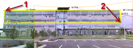
To ensure the highest accuracy, you should select coordinates that are as horizontally far apart on the surface as possible. And, although the vertical plane is infinite, you should select points as vertically far apart as possible to make the depth plane clearly visible in the Station View. In the following example, the user has specified a depth plane that extends across the entire width of the building facade and is tall enough to be clearly visible.
Note: Be sure to select coordinates that are on the same surface you want to use to create the depth plane. For example, if you select the first coordinate on an exterior facade and then select the second coordinate on a facade that is inside a recessed entrance way, the depth plane will not accurately represent the non-recessed exterior facade.
- Click Create.
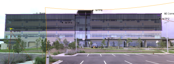
The new depth plane is represented by a shaded rectangle in the Station View and is now available for selection in the Plane drop-down list.
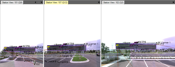
Note that the depth plane is displayed in all station views.
You are now ready to create linework or make measurements.
- Select <<Define new depth plane>>.
- Use the appropriate tool on the CAD ribbon to create linework or make measurements on the surface(s) represented by the selected depth plane(s).
These entities can be selected and exported if necessary.
Note that your line work or measurement can start on a surface represented by one depth plane and continue or end on a surface represented by a different depth plane. Simply select the various depth planes as you create the CAD object or make a measurement.
Measure Points Using Photogrammetry
