Understanding Breaklines
Breaklines are lines that help to define the shape of surfaces by controlling how triangles in the surface mesh are formed; triangles forming a surface never cross a breakline. Use breaklines to make surfaces more accurate. For example, if a square area on your surface is formed by two triangles using the wrong opposing points, you can switch the direction of the diagonal to reform the two triangles. This might be done to get drainage to work as the site designer intended, or simply to ‘smooth’ the surface.
The simplest way to create a breakline is to add it between points where surface triangles converge (vertices). You can also create breaklines by picking locations on the surface that are not vertices. The surface triangles are redrawn, creating vertices at the points you picked.
You might add a breakline to a surface to represent:
- A stream bed
- A curb line
- A linear feature that was not recorded in the field
|
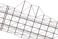
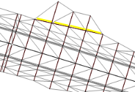
Here is an example of how adding a breakline (in yellow) can change a surface: |
|
|
|
|
In addition to the breaklines that you actively create, other breaklines are automatically created in surfaces when you import or select linear objects to create a surface. Any linear object, such as a polyline or an alignment, that you use in the creation of a surface will be represented as a breakline in the surface. If you modify the linear object, the breakline will update in response.
Note: When you use an alignment in the creation of a surface, you can constrain the resulting breaklines horizontal and vertical distance from the alignment by setting tolerances in the Project Settings. Select Project Settings in the Quick Access Toolbar. Then click Computational Settings and Surface in the left pane.
