Edit a Surface by Creating a Breakline
3D lines of several types can be designated as members of a surface. They serve to influence the shape of that surface by acting in the classic manner as breaklines. These lines can exhibit complex curvilinear geometry and still serve a breaklines, by employing the breakline approximation parameters as defined in the computational settings for a surface in the Project Settings dialog.
One of the types of lines that can serve as a member of a surface, thereby acting as a breakline, is the linestring. Like alignments, linestrings can exhibit rather complex curvilinear geometries. But they can also exist as simple strings of straight line segments, connecting 3D coordinate locations, as in the case of the more classic breaklines associated with typical TIN models. A linestring of that nature is referred to here as a simple breakline; a specific command has been devised to allow you to create a linestring of that nature and assign it as a member of a surface at the same time, while defining its surface sharpness. In using the Create Simple Breakline command, you will in fact be creating a linestring object, though through a simpler user interface and one that supports the line's association with a surface as a part of its creation.
The easiest way to create a simple breakline is to add segments between surface vertices (the points where surface triangles converge), but you can also add linestring segments freely between any two locations on or near the surface. Any geometric edit to a breakline of any kind will cause the entire surface to be reformed.
Prerequisites:
- Surface
To create a simple breakline:
- Select Create Breakline in Surfaces > Create.
The Create Breakline command pane displays.
- In the Name box, type an identifier for the linestring as you want it to appear in the Selection Explorer and in graphic views when you select from multiple objects. You can also use the name to select the linestring in the Advanced Select command.
- Select a layer on which to create the linestring in the Layer list, or select <<New Layer>> to create a new layer for the linestring.
- Select an option for how smoothly the surface is rendered at the linestring in the Surface sharpness list.
- Select the surface to which the linestring will be assigned as a member in the Add to surface list.
- Click . The Edit Linestring command pane displays with reduced options appropriate for creating a simple breakline
- In the Start Point group's Type list, select Coordinate to start the breakline using any location, or select Point ID to start the breakline using a named point.
- Click in either the Coordinate box or Point ID box (depending on what you chose for the starting point type), and use one of these ways to specify each point along the breakline:
- In a graphic view, pick a vertex on the surface, or pick a named point (may also be a vertex)
- Pick any location on or near the surface in the graphic view, and then type an elevation in the Elevation box. Then, click Save or press .
- Type a coordinate, press , and type an elevation in the Elevation box or right-click for COGO elevation options. Click or press .
The first point of the linestring is saved and you are prompted to add the second point and specify how the segment between them is formed.
Note: To use the elevation from a point you pick anywhere on a surface, right-click and select From Surface Snap from the context menu. You are prompted to pick the point in the From Surface Snap command pane. Then, click Save or press .
Note: To avoid picking points off of the surface (with no elevation), uncheck the Free snap in the Snap Mode dialog when you create a breakline. If you are prompted for an elevation, you may have missed the vertex point you were trying to pick.
Note: You can also draw a 'freehand' breakline without using any existing data using method below. In fact, you do not even need to have a surface to create a breakline. - Keep adding segments to the breakline using one of the methods in step 8.
- Click . The breakline appears on the surface in graphic views, but does not appear in the Project Explorer.
Note: Once created, breaklines can be graphically selected and added to other surfaces.
Note: To see the properties of a breakline (in the Properties pane) you have actively created, select the breakline in a graphic view.
Tip: To view changes to your surface more clearly as you work, open a 3D view and move it to a new tab group next to your plan view so you can see both views concurrently.
To edit a simple breakline:
- Use the operations in Edit a Horizontal Linestring.
Breakline approximation parameter:
The breakline approximation tolerance is the maximum horizontally measured distance that a breakline approximation of a lines can deviate from the line itself. Depending on the needs of your model, you may determine that this tolerance makes a surface more or less complex/accurate than you need.
- To change breakline approximation parameters, select Project Settings in the Quick Access Toolbar.
- In the Project Settings dialog, click Computations and then Surface in the left pane.
- In the Horizontal tolerance box for Breakline Approximation Parameters, change the setting, and click .
Note: You can also set a vertical breakline approximation tolerance here.
- Experiment with different breakline approximation tolerances until you find one that reflects the curves of your data without making the surface overly complex.
|
|
|
|
|
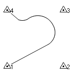
The member objects |
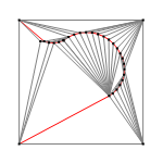
The resulting surface with a horizontal breakline approximation tolerance of 0.02. |
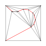
The resulting surface with a horizontal breakline approximation tolerance of 0.2. |