Export Excavator Profile (.profile) Files
Excavator profile files (.profile) contain 3D point data specifying target depths along a road alignment or other corridor. Using this data, a hydraulic excavator can set up (on a setup line) at intervals along the specified alignment and dig sample cross-sections at the target depths. Graders can then remove earth between these cuts (the 'profiles') to create the subgrade for the roadway.
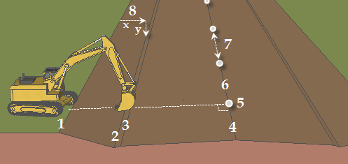
- Setup line
- Line picked for the first cut depth
- Line picked for the second cut depth
- Line picked for the third cut depth (a 3D alignment can be picked)
- Begin station (on the setup line, perpendicular from the alignment)
- Alignment
- Station intervals for setups
- Delta offset (x) and delta elevation (y) from the setup line at each station interval are exported
To export an excavator profile file:
Note: For general instructions on exporting data files, see Export Data.
- Select Export in Home > Data Exchange.
The Export command pane displays.
- Click the Construction tab. The available exporters appear.
- Select Excavator Profile exporter in the File Format list.
- In the Data group, select the reference alignment for the corridor to be excavated in the Alignment list (6 in the diagram above).
- Click in the Setup line box, and pick the 3D line that the excavator will set up along in the Plan View (1 in the diagram).
Next, you will select the lines that specify the target depths to which the excavator will dig. Often, the setup line and lines indicating the target depths will be parallel.
- Click in the first box under Lines.
- In the Plan View, pick the first 3D line that you want the excavator to dig to at each station interval (2 in the diagram, the closest line to the setup line).
- In the next box, pick the next 3D lines in the view (3 and 4 in the diagram).
- Repeat step 7 until you have specified all of the lines that indicate the depth to which the excavator should dig.
Note: The profile that appears on the excavator's system will be drawn connecting the lines in the order they were picked in this software. In the field, the excavator's operator can choose to bench on any of the lines and can flip the profile to dig it in the opposite direction.
- Click in the Begin station box and pick a point along the alignment, or type a value in the box, for the first station along the alignment at which you want the excavator to dig (5 in the diagram).
- For the final station, pick another point along the alignment, or type a value in the End station box.
- In the Station Interval box, type a value for the interval (horizontal distance along the alignment between setup locations) at which the excavation should be done (7 in the diagram).
Note: If the total distance between the beginning station and end station is not divisible by the interval, the distance between the penultimate and final excavation points will be less than the interval. For example, if the beginning station is 0, the ending station is 70, and the interval is 20, excavation points are created at 0, 20, 40, 60, and 70, the final interval being 10 rather than 20.
- Type a path and file name for the exported file in the File Name box, or click the
 icon to browse for a location and specify a file name.
Note: To be used in GCS900, excavator profile files must be exported to a folder named "
.profile".If a .profile folder does not exist, you cannot create it in Windows® Explorer; it must be created from the Windows command line. Click Start > Run. Typecmdand press [Enter]. At the DOS prompt, typemkdir .profileThe folder is created at the root level and can then be moved to any location using Windows Explorer.
Note: Excavator profile files can be exported to compact flash data cards used on excavators.
Note: A file is created for each depth to be cut at each station interval. By default, the exported files are given the name of your project, plus the station value at each interval. - If you want to export another file after this one, uncheck the Close command after export box.
- In the Settings group, set export properties, as needed.
- Click Export. 3D points are exported; they are calculated as a delta offset (x) and delta elevation (y) from the setup line at each station interval (z) (8 in the diagram).
