Understanding Surface Densification
When you densify a surface, a finer mesh of triangles is created in areas where changes in the surface's shape were previously represented by the Remove diagonal and Adjust for arc/chord properties. Densification better represents the discrepancies between arcs in the alignment and chords created in the surface to represent the arcs, and also models torsional changes in a surface when triangles are twisted. These images show an example of surface densification (as seen in the Plan View).
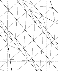 Surface before densification Surface before densification |
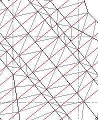 Surface after densification Surface after densification |
The differences between a surface before and after densification will also be apparent in surface contours, the Surface Slicer View, and earthwork reports.
Note: Some types of surfaces cannot be densified. These include:
- surfaces created from imported surface data, such as that contained in a .ttm file, that are comprised of internal data
- dependent surfaces, such as uncompacted PCS surfaces, which rely on two existing surfaces. In this case, you can densify, in effect, the dependent surface by densifying the two surfaces on which it depends.
Note: To densify a surface, it must be linked to an alignment because cross-sections used in the densification are calculated at stations along the alignment; if the Horizontal alignment property is set to None, the Densification group is disabled.
Note: Surface densification is intended for (and works best on) road / corridor surfaces which have breaklines running along the associated alignment and do not contain intersections.
Densifying Surfaces for Field Data
The intent in densifying a surface is to create a surface object for export to field software that accurately reflects the surface you see in this office software. When you prepare data to export to the field, you should densify the surfaces and road surfaces to assure that they achieve suitable and similar accuracy and precision in both SCS and GCS. To understand the risks in sending undensified surfaces to field software, see Surface Cross-sections Issue in Field Data.
