Project Cleanup Options
Use these options to automatically clean up your imported CAD data. The actions can be applied to selected objects or your entire project.
|
Options |
|
| Objects to process |
Specify whether you want to clean up objects that are currently selected or all of your project data. Include sheet views - Check this box to run project cleanup not only on model space objects, but also on paper space objects, typically be on imported sheets. |
| Remove unused block definitions |
Check this to delete all block definitions that no objects are referencing. Removing unused or unneeded objects helps to reduce the visual clutter of your data and the size of your project file. |
| Remove unused line styles |
Check this to delete all line styles that are not assigned to lines. |
| Remove unused text styles |
Check this to delete all styles that are not being used by CAD text objects. |
| Remove zero length and fragment lines Length tolerance |
Check this to delete all lines that have a length less than the specified tolerance.
Then specify the shortest allowable line length in the Length Tolerance box. |
| Remove duplicate lines |
Check this to delete redundant lines. One line out of each set of duplicates is retained. |
| Remove overlapping line loops |
Check this to break lines that overlap themselves into two separate linestrings. |
| Remove unprotected layers with no objects |
Check this to delete all empty layers. |
| Join lines with small gaps, overlaps, and misalignments Misconnection correction tolerance |
Check this to merge two (and only two) lines that share an end point into one linestring. The lines must be on the same layer to be joined.
Then specify the distance within which the end points are considered to be the same point. |
| Remove blank text objects |
Check this to delete CAD text objects that contain no characters. |
| Remove hatch objects |
Check this to remove hatch objects used by other software programs. |
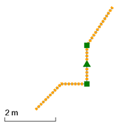
| Filter line vertices Include CAD splines Circle filtering radius |
Check this to delete redundant points between two line segments where the point does not deviate from the previous segment's tangent by more than the specified tolerance. Check this to filter not only polylines, but also splines. Then specify the horizontal/radial distance that a node must deviate from the previous segment's tangent in order to be retained in the Cylindrical tolerance box.
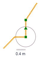
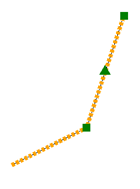
Original line Line with 0.4 m filter applied
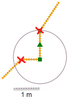
Line with 1 m filter applied 1 m filtered line |
| Set elevation outside range to undefined Minimum elevation Maximum elevation |
Check this to set the elevation on all objects that fall outside of the specified elevation range to undefined (?) elevation. Then type values in the Minimum elevation and Maximum elevation boxes. |
| Scan for elevation range |
Click this to find the elevation range of your data, The results appear in the Minimum elevation and Maximum elevation boxes. |
| Clear Defaults Apply |
Click these buttons (respectively) to:
|
| Status |
This displays the results of the cleanup after you click Apply. |