Connectors and LEDs
Antenna connector
The radio has a single TNC female type antenna connector with impedance of 50 Ohm.
The antenna should always be connected when the power is on. Removing the antenna while the transmitter is on may damage the power amplifier inside the transmitter.
Power supply
The radio will consume electric power when connected to a power supply. The amount of power consumed depends on the operational mode. Highest power consumption is while the transmitter is active, and output RF-power level is set to maximum. Even higher power is drawn from the power supply in a moment when the radio is being connected to a power supply. This so-called inrush current can be several times higher than normal current consumption, but will last only few milliseconds. For proper operation it is crucial to ensure that the power supply has output power rated to higher than the maximum power consumption of the device and that the power supply can handle short inrush currents properly.
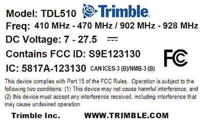
The TDL510 radio operating voltage range is +7 to +27.5 V DC / -15 % / +20 %.
NOTE – As a result of new revision of safety standard IEC600001, voltage range is now marked with wider tolerance limits. For minimum and maximum operating voltage, see Specifications.
As an increased safety feature, it is recommended to add a fuse between the power supply and the TDL510. This ensures that both, the device and the power supply, is protected against over current situations. The recommended fuse size is 2 Amps.
The operating voltage range is also shown on the back of the radio:
LED modes
There are five LEDs that show the status of the serial port and radio:

|
LED |
Indication |
Off |
Red |
Orange |
Green |
|---|---|---|---|---|---|
|
RTS |
RTS-line status (D15 Pin 13) |
Inactive |
Active |
- |
- |
|
CTS |
CTS-line status (D15 Pin 6) |
Inactive |
Active |
- |
- |
|
TD |
TD-line status (D15 Pin 11) Indicates that the radio is receiving data via serial port. |
No data |
Data |
- |
Test Tx active |
|
RD |
RD-line status (D15 Pin 9) Indicates that the radio is sending data via serial port. |
No data |
Data |
- |
- |
|
CD |
Indicates the status of the radio interface. Note that the status of CD-line (D15 Pin 2) may differ from the status of CD LED. |
No signal |
Transmitter is ON |
Noise |
Reception |
|
Base |
TD will flash red at 1 Hz (data incoming from base on port 1), then CD will flash red immediately (radio Tx) |
|
|
|
|
|
Repeater |
CD will flash green (radio Rx), then RD and CD will flash red immediately (data sent to port 1 and radio Tx) |
|
|
|
|
D15 connector
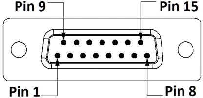
15-PIN FEMALE D CONNECTOR PINOUT:
The I/O column below denotes the direction of the signal:
-
"IN" is from DTE (Data Terminal Equipment) to the radio.
"OUT" is from the radio to DTE.
|
PIN |
Name |
I/O |
Level |
Explanation |
|---|---|---|---|---|
|
1 |
DTR |
IN |
MAX +27.5 V |
Data Terminal Ready. This pin can be used to wake-up the radio from standby mode. >+3 V DC or not connected = ON |
|
2 |
CD |
OUT |
RS-232 |
Carrier Detect |
|
3 |
RD2 |
OUT |
RS-232 |
Port 2 receive data |
|
4 |
TD2 |
IN |
RS-232 |
Port 2 transmit data |
|
5 |
- |
- |
- |
Not used. |
|
6 |
CTS |
OUT |
RS-232 |
Clear to send. This signal indicates that the radio serial interface is ready to receive data from DTE. |
|
7, 8 |
GND |
- |
- |
Operating voltage ground / signal ground. Signal ground has a galvanic connection to the modem casing. |
|
9 |
RD1 |
OUT |
RS-232 |
Port 1 receive data to DTE from the radio. |
|
10 |
DSR |
OUT |
RS-232 |
Data Set Ready. Indicates that the radio is ON. |
|
11 |
TD1 |
IN |
RS-232 |
Port 1 transmit data from DTE to the radio. |
|
12 |
MODE |
IN |
MAX +27.5 V |
<2 V DC or connected to ground = programming mode >3 V DC or not connected = Data transfer mode Programming mode is for bringing the modem to a serial port state: Data port 1 38400N81. By default, modem is Data transfer mode in a case Pin 12 is floating. |
|
13 |
RTS |
IN |
RS-232 |
Request To Send from DTE. RTS and CTS signals apply to the selected data port only (port 1). |
|
14, 15 |
Vb |
- |
See Specifications |
Operating voltage 7 to 27.5 V DC |
TIP – Unused pins can be left unconnected.
