Add a basic alarm
To add a new alarm, complete the following steps.
Step 1: Add the alarm definition
-
Click the Add Alarm Definition button.
-
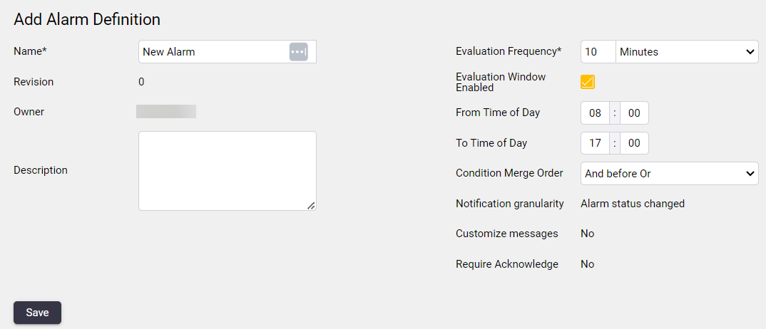
In the Add Alarm Definition page, fill out the fields for the new alarm:
-
Name: Enter a name for the alarm that is unique in the project.
-
Description: Enter a description of the alarm.
-
Evaluation Frequency: Select the rate at which the alarm checks whether or not the conditions for the alarm are satisfied.
-
Evaluation Window Enabled: Enable an evaluation time window if you want the alarm to evaluate observations only in a particular time interval per day. Only observations inside this daily interval are evaluated by the alarm, and any observations outside this time interval are ignored by the alarm.
If the To Time of Day is less than the From Time of Day then the interval wraps around midnight starting at the To Time of Day and ending on the From Time of Day of the next day.
-
Condition Merge Order: Select how the statuses of individual alarm conditions belonging to this alarm definition are rolled up in order to determine a state for the alarm definition.
-
-
When you are done entering alarm information, click Save to move to the next tab.
Step 2: Configure the alarm condition (General)
-
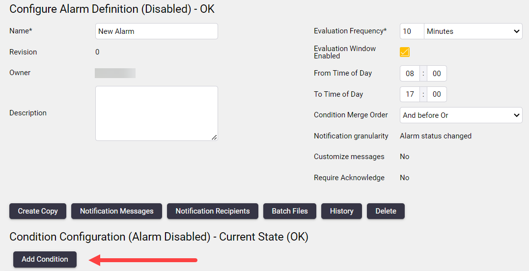
In the Configure Alarm Condition page, click the Add Condition button:
-
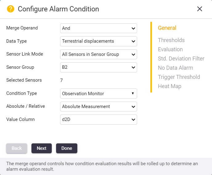
The Configure Alarm Condition page shows the General tab. Complete the fields:
-
Merge Operand: The merge operand controls how condition evaluation results are rolled up to determine an alarm evaluation result. For the first condition it is not applicable, but any additional conditions can be concatenated via the logical Boolean operators AND or OR.
-
Data Type: The Data Type which you wish to monitor with this alarm condition.
-
Sensor Link Mode: The Sensor Link Mode allows you to link this alarm condition to specific sensors, all sensors of a selected Sensor Type, or all sensors of in a selected Sensor Group (see Sensor groups).
In the example above, we selected All Sensors in Sensor Group as the Sensor Link Mode and we selected S Group Sensor as the Sensor Group, with 4 Selected Sensors.
-
Condition Type: The Condition Type can be by the Observation (default) or by the Velocity calculated from the observations.
You can monitor velocities only if you selected a Positional Data Type for this alarm condition. Velocity values are calculated as the slope of a linear regression line fitted to observation values within a rolling time window. A new velocity value is calculated with each new observation value that becomes available.
-
Absolute / Relative: Monitor absolute or relative measurements.
-
Value Column: The Value Column which you wish to monitor with this alarm condition.
-
-
Click Next to move to the next tab.
Step 3: Configure the alarm condition (Velocity)
If you selected the Observation Type as Velocity in the previous tab, the Configure Alarm Condition page shows an additional tab called Velocity.
-
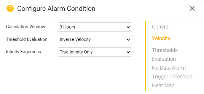
Configure the fields in the Velocity tab to determine how the velocity is calculated and presented:
-
Calculation Window: Specify the width of the rolling time window over which a linear regression line should be fitted in order to calculate the velocity to be monitored.
-
Threshold Evaluation: Specify whether the alarm condition thresholds should be configured in terms of Velocity (v) or Inverse Velocity (1/v).
-
Infinity Eagerness: Applicable for Inverse Velocity. This property controls how soon infinity is assumed when a value close to zero is inverted.
-
-
Click Next to move to the next tab.
Step 4: Configure the alarm condition (Threshold)
-
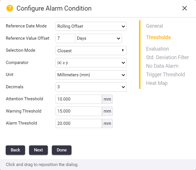
The Configure Alarm Condition page shows the Threshold tab. Complete the fields:
-
Reference Date Mode: If relative measurements were selected in the previous option, you can specify the reference date mode as Rolling Offset or Specific Date here.
-
Reference Value Offset: If Rolling Offset was selected for Reference Date Mode in the previous option then you can set the reference date offset here.
-
Reference Date: If Specific Date was selected for Reference Date Mode, then you can enter the fixed Reference Date here.
-
Selection Mode: If relative measurements were selected, then you can choose how the reference value is selected here.
-
Comparator: Specify the comparator that should be used to evaluate the alarm condition. Here X denotes the measurement that might trigger the alarm and Y denotes the threshold or specific value with which X is compared.
-
Unit: The unit used to define thresholds for the alarm condition.
-
Decimals: The number of decimals used to define thresholds for the alarm condition.
-
Thresholds: The Threshold fields specify the three states that the condition can trigger, starting at Attention, then Warning and finally Alarm.
-
-
Click Next to move to the next tab.
Step 5: Configure the alarm condition (Evaluation)
-
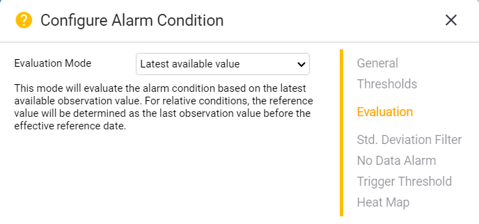
The Configure Alarm Condition page shows the Evaluation tab. Select the Evaluation Mode:
-
Latest available value: Evaluate the latest available observation for the sensor(s). In this mode using relative values, the reference value is the last observation value before the effective reference date.
-
Average of X latest values: This mode evaluates the alarm condition based on the average value of the last X number of observations.
-
Peak (any): This mode evaluates the alarm condition based on the most severe peak value (high or low) that occurred since the previous evaluation.
-
Peak (local maximum): This mode evaluates the alarm condition based on the highest value that occurred since the previous evaluation.
-
Peak (local minimum): This mode evaluates the alarm condition based on the lowest value that occurred since the previous evaluation.
In the last four evaluation modes listed above, if using relative values, the reference value is determined as the average of the last X observation values before the effective reference date.
The Peak evaluation modes are useful for monitoring sensors with observation frequency higher than one observation per minute, such as accelerometers.
-
-
Click Next to move to the next tab.
Step 6: Configure the alarm condition (Standard Deviation Filter)
-
The settings on the Standard Deviation Filter tab allows you to configure the alarm condition to not trigger the alarm on poor quality observations.
When standard deviation filtering is enabled, observations with standard deviations larger than the filter value are ignored by the alarm evaluation process. This filtering is applied regardless of the selected evaluation mode (latest, average or peak) and is used to obtain both the observation value and the reference observation value (for relative conditions).
Setting this value too low may result in a scenario where no observations are detected - which may cause a configured No Data alarm to trigger. For more information, see Step 7: Configure the alarm condition (No Data Alarm) below.
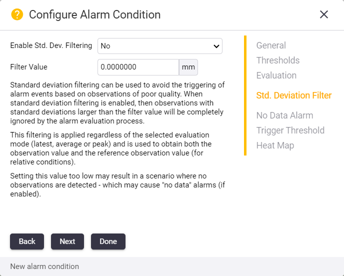
The available fields are:
-
Enable Std. Dev. Filtering: Specify whether standard deviation filtering should be enabled.
-
Filter Value: Observations with standard deviations larger than this value will be ignored by the evaluation of this alarm condition.
-
-
Click Next to move to the next tab.
Step 7: Configure the alarm condition (No Data Alarm)
-
The No Data Alarm tab allows you to enable a No Data Alarm to be raised if the sensor did not receive any data for the specified period of time. Complete the fields as required.
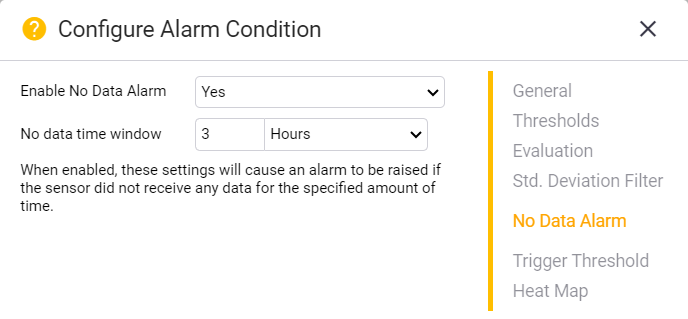
The available fields are:
-
Enable No Data Alarm: Specify whether a no data alarm should be triggered.
-
No data time window: If no observations are found for this window of time, then a No Data Alarm is triggered.
-
-
Click Next to move to the next tab.
Step 8: Configure the alarm condition (Trigger Threshold)
-
The Trigger Threshold tab allows you to configure the alarm condition thresholds to trigger when sensors violate the condition threshold.
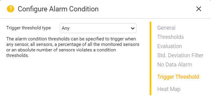
The available choices are:
-
Any monitored sensor.
-
All monitored sensors.
-
A Percentage of monitored sensors.
-
An absolute Number of monitored sensors.
-
-
Click Next to move to the next tab.
Step 9: Configure the alarm condition (Heat Map)
-
The Heat Map tab allows you to configure a Map Layer that represents the particular Alarm Condition.
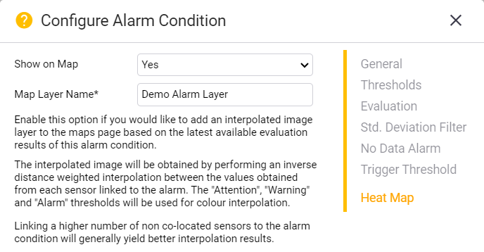
Select Yes to show this alarm condition as a heat map layer and then enter the name for the map layer.
Step 10: Complete the alarm condition configuration
Click Done to complete the alarm condition configuration.
The Alarm Condition you have configured is shown in the table at the bottom of the Alarm Definition page.
