Create Stored Cross-sections Along an Alignment
Use the Create Stored Cross-section command to create a stored cross-section at a specific station along an alignment.
|
|
|
|
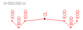
Stored cross-section with named nodes |
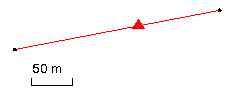
Current stored cross-section indicator on an alignment in the Plan View |
Typically, you will create cross-sections by entering tabular station, elevation, and offset data for the purpose of creating a simple road surface for calculating takeoff earthwork volumes.
Prerequisites:
- License; See the Subscription Plans page. For a license matrix by command, see the License page in the TBC Community. Also see View and manage licensed features.
- Horizontal alignment (HAL) along which to create the cross-section
- Cross-section data, such as a station, elevation, and offset table
To access the command:
- Select Create Stored Cross-Section in Corridors > Cross-Section.
- Right-click an alignment, and select Create Stored Cross-Section from the context menu.
To create a cross-section:
- If applicable, import any cross-section data that you already have for the alignment, such as in a .reb file, before you start the command.
- Select the alignment along which to create additional cross-sections in the Alignment list.
- Specify the station at which to create the cross-section in the Station box.
- Select the layer on which you want the cross-section to reside in the Layer list, or select <New> to create a new layer.
- Click OK. The Stored Cross-section Editor displays.
- In the first row, click in the Offset box and specify a distance from the alignment (usually a road centerline) at which to place the first node of the cross-section.
- In the Elevation box, specify the elevation of the first node.
- Optionally, name the first node, such as EOP for edge of pavement, in the Name box.
- Repeat steps 6 - 8 until the cross-section at the specified station is complete.
Note: For any cross-section, you can enter information for nodes in any order; Nodes are sorted from left to right based on the offset.
Note: By default, the vertical exaggeration of the Stored Cross-section Editor view is set to 5. To change this, click the Project Settings icon to access the Cross-section View Project Settings. - If needed, add the cross-section to a surface using the Add/Remove Surface Members command.
- To create another cross-section, click Create Cross-section. Thenreturn to the command pane and repeat the preceding steps.
- To move between cross-sections in the Stored Cross-section Editor, click Previous and Next.
- To hide or show segments between nodes, click the Project Settings icon. In Project Settings's Cross-section Editor Grid Options , set Visibility column to Hide or Show. When set to Show, the Visibility column appears in the editor.
Options:
- Alignment - Select the alignment for which you have cross-section data to enter.
- Station - Specify the station for each set of cross-section values, as indicated in your cross-section data.
- Offset - For the current station, specify the distance from the alignment for each node on the cross-section. Use negative numbers for nodes to the left of the alignment (typically a road centerline).
- Elevation - Specify the elevation of each node.
- Name - Specify the name or abbreviation of the node. Nodes with identical names are linked from cross-section to cross-section along the alignment.
Connecting stored cross-sections
The connection type from each stored cross-section to the next cross-section is set in the Properties pane. These connections are only as good as the similarity between each pair of cross-sections; if segments nodes, and labels match from cross-section to cross-section, the connections will be good. After you create and connect multiple cross-sections along an alignment, check the connections!
Scenarios:
- If the HAL has vertical alignment (VAL) data as well, a dot in the Stored Cross-section Editor's graphic indicates its position.
- When you create a second cross-section (or more) cross-section along the same alignment, connections are drawn between the nodes on the original cross-section and any corresponding nodes on the new cross-section. You can control the visibility of these connecting lines in the Properties pane for the original cross-section.
- If you import or create stored cross-sections at stations that are beyond the extents of their associated alignment, the cross-sections are denoted by a triangle icon at the beginning of the alignment (the cross-sections themselves are not actually drawn). To select one of the stored cross-sections, ‘window’ around the icon in the Plan View and pick the cross-section in the Selection Explorer.
