Understanding Holes, Islands, and Overlapping Areas
This software provides a number of native line objects, which are or can be made to form a closed line. These include boundaries, which are inherently closed, and other objects such as linestrings or polylines, which can be closed. The term area, as used in the discussion below, refers to the region encompassed by a closed line. There are a significant number of different purposes for which you may wish to designate an area and therefore the boundary within which it lies. These might include an area of a known specific purpose, such as an avoidance zone, or just boundaries that you may wish to employ to limit the extents over which an analysis of some sort is to be performed.
If any of the different types of areas that you create overlap or encompass one another, their types and the spatial relationships between them, dictate how they affect each other, the formation of surfaces that they affect, or calculations based on those areas.
Surface boundaries:
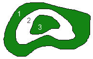
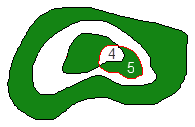
The area of coverage of a surface can be limited by employing one or more surface boundaries, using the Add/Remove Surface Boundaries command. The software uses simple logic to non-destructively limit a surface’s area of coverage, based on the assigned surface boundary or boundaries. This can limit the surface’s area, break it into multiple portions, and create nested holes and islands within larger areas that encompasses them.
|
|
|
|
The green above represents surface area. The white represents area without surface triangles.
|
|
The easiest way to understand the nuances of surface boundaries by simply creating a few boundary objects that are:
- encompassed within a surface,
- encompassing a surface,
- overlapping onto a surface, and
- encompassed within or overlapping other surface boundaries.
Those boundary objects can then be added and removed as surface boundaries and the effects will be seen immediately. Use the Create Surface Edge Breakline command to create a boundary around the surface’s perimeter and use it as one of the surface boundaries. Perform experimentals on a surface for which the wireframe is displayed, one that is shaded, and one for which contours have been drawn. Note the effects on all aspects in which the surface is manifest in the Plan View and 3D View. Then use the Surface Slicer View to slice through the surface while various surface boundaries are in force. Note that those boundaries non-destructively influence every aspect of the surface’s manifestation, including those related to volume computations, etc. Move some of the surface boundaries to discover how the effect is dynamic and completely non-destructive of the underlying surface data, which is never altered.
