Create and Edit Surface Contours at an Interval
Use the Create Quick Contours command to add contour lines to a surface at regular elevation intervals. This command creates a single object containing all of the contours, which is handy for quickly visualizing existing topography or when you are still making edits to a design surface. You can explode quick contours to edit the individual lines.
Use the Create Contours command to create contour lines that include elevation labels and colors. You can then adjust the positions of the contour labels for optimal plotting. This command creates individual, editable line and text objects that are useful when you are ready to plot a finished surface.
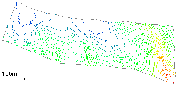
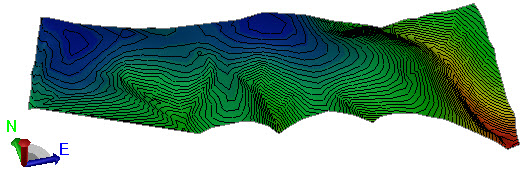
Contours are lines that show the topography of a surface at a constant elevation. Contour objects are separate from the surface objects to which they are attached, but they are nested under surfaces in the Project Explorer. You can associate multiple contour objects with a single surface object. When a surface is changed, the contours on the surface update to reflect any changes in elevation.
Tip: To smooth quick contours, first explode them using the Explode command. Then use the Toggle Segments Straight/Curved option in the Edit Linestring command.
Prerequisites:
- Licensed module; See the Subscription Plans page. For a license matrix by command, see the License page in the TBC Community. Also see View and manage licensed features.
- Surface
To access the commands:
- Do one of the following:
- Select Create Quick Contours in Surfaces > Contours.
- Right-click a surface, corridor, or cut/fill map and select Create Quick Contours from the context menu.
- Select Create Contours in Surfaces > Contours.
- Right-click, and select Create Contours from the context menu.
To create quick contours:
- Select or confirm the surface to which you want to add contours in the Surface list.
- Type a name for the contour object in the Name box.
- Type a value for the vertical distance between contours in the Contour interval box. The Estimated number of contours value updates in the Surface Information group below.
- Type a value for the spacing of index contours in the Index frequency box. Index contours are the major contours, while the other contours are the minor contours.
- Select a layer on which to place the contour object in the Layer list.
- Select a display color for the contours in the Contour color box.
- Select a display color for the index contours in the Index color box.
- Click . The contours appear on the surface in graphic views, and under the surface in the Project Explorer.
To create contours with elevation labels and colors:
- Select or confirm the surface to which you want to add contours in the Surface list.
- Type a name for the contour object in the Name box.
- Type a value for the vertical distance between contours in the Contour interval box. The Estimated number of contours value updates in the Surface Information group at the bottom of the pane.
- Type a value for the spacing of index contours in the Index contour frequency box. Index contours are the major contours, while the other contours are the minor contours.
- Select a layer on which to place the contour object in the Layer list.
- Select a display color for the minor contours in the Contour color box.
- Select a thickness for the minor contours in the Contour line weight list.
- Select a color for the major contours in the Index contour color list
- Select a thickness for the major contours in the Index contour line weight list.
- To override the specified contour and index contour colors and color the contours by elevation, check the Color contours by elevation box.
- To round the contours at each vertex, check the Smooth contours box.
- Confirm the style of the labels or select a new one in the Text style list.
- Specify a Distance between labels.
- To add additional elevation labels at the extents of the contours, check the Label ends of contours box.
- Select a display color for the index contours in the Index color box.
- Click . The contours appear on the surface in graphic views, and under the surface in the Project Explorer.
To edit quick contours:
- Do one of the following:
- Double-click the contour object in the Project Explorer, or right-click a quick contour in the explorer or a view and select Properties from the context menu. In the Properties pane, edit any available properties as needed.
- Pick a quick contour, right-click and select Explode from the context menu. Right-click individual lines and select Edit to make changes.
To edit contours:
- Pick a contour line or elevation label in a graphic view, right-click, and select one of the following from the context menu:
- Properties - In the Properties pane, edit any available properties as needed.
- Edit - Make changes in the linestring editor or text editor.
Note: Editing a smoothed contour as a linestring can result in an excessive number of vertices along the linestring.
Scenarios:
- If you create surface contours with elevation labels and then update surface or the elevation format (Project Settings > Units > Coordinates), the labels will not automatically update unless you have the Rebuild method for the contours set to Automatic in the Properties pane. You can also rebuild the contours manually from the Project Explorer by right-click the contour object and selecting Rebuild Contours from the context menu.
- If you modify a surface on which contours are based, you should update the contours. Right-click the contour object in the Project Explorer, and select Rebuild Contours from the context menu.
Note: When you rebuild contours, you will lose any edits you have made to the contours and their text labels.
Dependencies:
- Elevation colors for contour lines are defined per surface in the Edit Color Mapping command. If you edit the colors for a surface with contours colored by elevation, the contour colors will be updated.
