Utility Node - Fitting Options
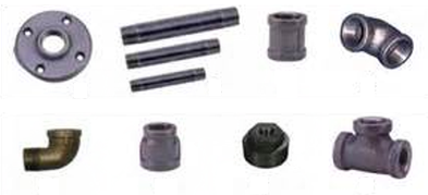
Use these options to define utility network node objects such as bends, tees, flange adapters, crosses, sleeves, reducers, caps, and plugs. For cable networks, fittings might include objects such as lugs, arresters, cut-outs, plugs, eyes, balls, shanks, sleeves, crimps, and clips. Count site improvements such as these are represented by discrete markers, such as points or CAD points, but can also reference CAD blocks in graphic views.
When placed in your model, each fitting is automatically oriented to its associated utility line and is drawn and defined by a user-defined block for the Plan, Profile and 3D Views. Fittings are primarily used for pressure and cable systems and have a single invert elevation.
Note: The fitting blocks supplied with the program have a scale of 1”. For an 8” valve you can apply a scale of 8 to the block. The insertion point of the block will be placed at the XYZ location of the node.
|
Options |
|
| Name |
This shows the descriptive name for the site improvement as it will appear in various commands that use utility nodes. These names should generally include size information to make object types easier to distinguish from each other. |
| Utility type |
Select a Type for the network you will use this node in; it will not appear as an option for other types of networks.
|
| Class |
Enter the industry type or rating of the fitting, e.g., pressure or thickness. |
| Color |
Select a default display color for the fittings as you want them to appear in graphic views. This can be changed in the properties for each object once they are created in your model. |
| Cost |
Enter the procurement cost of the fitting per unit. Note: This program displays the currency symbol and format that you have set in Microsoft Windows® Regional and Language Options. The units and calculations, however, are not associated with a specific currency, so if a project is opened on a computer with different regional settings, those currency symbol and formats are used, but no conversion between currencies has been made. |
| Plan View block |
Select a block to display at each fitting's location in the Plan View. If you do not have blocks in your project, see Import Block Definitions and Create a Block Definition. Typically, utilities are represented schematically with symbols. It is recommended that simple symbols are used so that display and printing times are minimized. Complex blocks can be used when detailed or realistic visualizations are desired. Note: By using the scale factor (below), a single block can be used schematically with various sizes of site improvements. |
| Scale |
Select a factor by which to scale the inserted blocks in the Plan View. 1.0 = 100% of the block definition's original scale when it was imported or created. |
| Profile View block |
Select a block to display at each fitting's location in the Profile View. Tip: You may want to name different versions of your blocks for their intended view, e.g., Fitting - Plan View, Fitting - 3D View. |
| Scale |
Select a factor by which to scale the inserted blocks in the Profile View. |
| 3D View block |
Select a 3D block to display at each fitting's location in the 3D View. |
| Scale |
Select a factor by which to scale (in X, Y, and Z) the inserted blocks in the 3D View. |
| Inspection criteria |
Inspection criteria is currently not implemented. |
| Diameter A, B, C, D |
For fittings with multiple dimensions that you want to inspect, check the boxes and specify the diameters. |
